Implant placement systems and one-handed methods for tissue fixation using same

a tissue fixation system and implant technology, applied in the field of endoscopic and arthroscopic surgery and suture anchor system and device, can solve the problems of not using the distal end of the driver to establish the graft position, suture tensioning and stabilization, etc., to prevent suture twisting, prevent relative motion, and maintain suture tension

Active Publication Date: 2017-10-10
TENJIN
View PDF24 Cites 9 Cited by
  • Summary
  • Abstract
  • Description
  • Claims
  • Application Information

AI Technical Summary

Benefits of technology

[0018]In operation, sutures placed in the graft are drawn into the distal end of the tensioning device. The elongate distal portion of tensioning device is inserted into a properly prepared socket in the target boney surface so that the distal end of the tensioning device, with its sutures is positioned at the bottom of the socket. Tension is then applied to the sutures by pulling on their proximal ends, which extend beyond the proximal portion of the tensioning device to move the graft into the desired position, namely into the prepared socket adjacent to the distal element of the tensioning device. The desired tension may be maintained by cleating proximal portions of the suture(s) into slots optionally formed in the handle of the tensioning device. The anchor (or interference screw) may then be screwed, threaded or otherwise driven into the socket, thereby trapping the sutures or graft between the anchor exterior surface and the socket wall. Critically, twisting of the suture(s) or graft(s) is prevented by the non-rotating distal tubular portion of the tensioning device that remains distal to the anchor distal end during anchor placement. In addition, tension on the sutures and the position of the graft are maintained during placement of the anchor throughout the procedure. After anchor placement, the driver and tensioning device are withdrawn, removed from the site, at which point the sutures may be trimmed to complete the procedure.
[0019]In contrast to the Burkhart and ElAttrache anchor systems, suture tensioning and establishment of the graft position are not accomplished using the driver's distal end or using an implant positioned in the driver's distal end. Rather, suture tension and graft position are established and maintained by the distal portion of a non-rotating tensioning device that extends beyond the driver and anchor distal ends. Because of this, the transmission of torque to the sutures and / or graft by the driver present in the Burkhart and ElAttrache systems is eliminated, along with its associated suture or graft spin.
[0020]The system and method of the instant invention provide a simplification over other currently available anchoring methods and hardware in that fewer steps are required and moreover the anchor has a simple, single-piece construction. The anchor system is scalable and, due to its simple construction, may be used with anchors smaller than those permitted using other currently available systems. The composition and construction in the anchor may be readily modified simply by changing the material from which it is constructed, by increasing or reducing the diameter or length of the anchor, by increasing or decreasing the wall thickness of the anchor, by modifying the profile of the exterior, or by any combination of these means. All such modifications are contemplated as within the scope of the present invention.
[0034]An anchor placement system of the present embodiment may also include a mechanism for releasably preventing relative axial and rotational movement between the driver and the tensioning device, such means optionally positioned within the cannulation (or “lumen”) of the driver. In a first condition, used during tensioning of the suture, relative axial and rotational motion is of the driver relative to the tensioning device is prevented. In a second condition, used during placement of the anchor, the driver may be advanced axially on the tensioning device to bring the anchor to the socket, and rotated to screw the anchor into the socket, with the tensioning device remaining stationery so as to maintain suture tension and prevent twisting of the sutures.
[0035]In a particularly preferred embodiment, prevention of relative motion is provided by a removable key having one or more protrusions, coupled with features formed on the handles of the tensioning device and driver such that, when the features are in alignment, engagement by the one or more protrusions of the key prevents relative axial or rotational movement between the torque-transmitting driver and the tensioning device. Removal of the key allows the driver to be advanced distally and rotated relative to the tensioning device. Other embodiments are anticipated in which other means are used to releasably prevent relative motion.
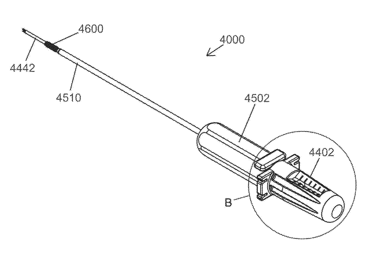
[0036]Certain preferred embodiments of the present invention are configured for one-handed operation by the surgeon. In these embodiments, a suitable tensioning device is irremovably (i.e., permanently) affixed to and / or positioned within an associated driver device, the driver device is axially movable between a first proximal position and a second distal position relative to the tensioning device. In the first proximal position, the distal portion of the tensioning device extends distally beyond the implant so as to allow tensioning of sutures and positioning of a graft as described previously herein as well as in related co-pending applications incorporated herein by reference. Advancing the driver distally toward its second, distal position brings the implant to the prepared socket in preparation for placement. Thereafter, the implant is threaded or axially driven into the socket. Distal motion by the driver relative to the tensioning device is resisted by a spring within the driver handle. The spring tension is sufficient to ensure that the distal end of the tensioning device remains in contact with the bottom of the socket to maintain graft position and to prevent rotation of the tensioning device during anchor placement.

Problems solved by technology

In contrast to the Burkhart and ElAttrache anchor systems, suture tensioning and establishment of the graft position are not accomplished using the driver's distal end or using an implant positioned in the driver's distal end.

Method used


Image

  • Implant placement systems and one-handed methods for tissue fixation using same
  • Implant placement systems and one-handed methods for tissue fixation using same
  • Implant placement systems and one-handed methods for tissue fixation using same

Examples


examples

[0209]The present invention attempts to address these afore-noted problems in the art. To that end, FIGS. 1A through 1C and 2A and 2B depict a cannulated driver 1500 for a knotless anchor system of the instant invention. Driver 1500 has a proximal handle 1502 in which is formed a proximal cylindrical recess 1504, and off-axis lateral holes 1506, and a tubular distal portion 1510 having at its distal end tubular drive element 1512. The distal portion 1514 of drive element 1512 is configured to be complementary to internal drive features 1602 in the proximal portion of the lumen of cannulated threaded anchor 1600; accordingly, torque supplied by driver 1500 is transmitted to anchor 1600. The distal portion of drive element 1512 may be fabricated in a variety of sizes, shapes, configurations and lumen sizes to suit a variety of anchors 1600, the requirements for a particular anchor 1600 depending on its size, configuration and material properties. For example, the complementary drive e...


PUM


Abstract

Described herein is a simplified placement system and method for a tissue graft anchor by which a surgeon may introduce one or more sutures into a hole in a boney tissue, apply a precise amount of tension to the sutures to advance a soft tissue graft to a desired location, and then advance the anchor into the bone, preferably while maintaining the requisite pre-determined suture tension and without introducing spin to the suture. Particularly preferred embodiments allow for the one-handed operation. To that end, embodiments in which relative axial movement between the inner tensioning device and outer driver device is optionally physically constrained, for example by means of cooperating and / or compressive elements disposed in the respective hub and handle portions, are described herein.

Description

PRIORITY[0001]This application is a continuation-in-part of U.S. patent application Ser. No. 15 / 012,060 filed Feb. 1, 2016 (now U.S. Pat. No. 9,566,066 issued Feb. 14, 2017), which, in turn, is a continuation-in-part of U.S. patent application Ser. No. 14 / 972,662 filed Dec. 17, 2015, which, in turn, is a continuation of U.S. patent application Ser. No. 14 / 636,389 filed Mar. 3, 2015 (now U.S. Pat. No. 9,226,817 issued Jan. 5, 2016), which, in turn, claims the benefit of U.S. Provisional Application Ser. Nos. 61 / 966,744 filed Mar. 3, 2014; 61 / 998,391 filed Jun. 26, 2014; 61 / 998,766 filed Jul. 7, 2014; and 61 / 999,405 filed Jul. 26, 2014, the contents of each of which are hereby incorporated by reference in their entirety. This application also claims the benefit of U.S. Provisional Application Ser. Nos. 62 / 284,151 filed Sep. 21, 2015 and 62 / 392,789 filed Jun. 11, 2016. The contents of the afore-noted priority applications are hereby incorporated by reference in their entirety.TECHNICAL...

Claims


Application Information

Patent Timeline
Patent Type & Authority Patents(United States)
IPC IPC(8): A61F2/08A61B17/04A61B17/00A61B17/06A61B90/00
CPCA61F2/0811A61B17/0483A61B17/0485A61B17/0401A61F2002/0888A61B2017/0088A61B2017/00477A61B2017/00526A61B2017/044A61B2017/0409A61B2017/0414A61B2017/0445A61B2017/0458A61B2017/0496A61B2017/06042A61B2090/034A61B2090/064A61F2002/0841A61F2002/0858A61F2/0805
Inventor DOUGHERTY, CHRISTOPHER P.HEISLER, GARY R.VAN WYK, ROBERT A.
Owner TENJIN
Why Eureka
Try Eureka