Heat-recovery-type refrigerating apparatus

a refrigerating apparatus and heat recovery technology, applied in the field of heat recovery type refrigerating apparatus, can solve the problem that electrical equipment items cannot be adequately cooled, and achieve the effect of reducing the number of spherical tubes and spherical tubes

Active Publication Date: 2017-10-10
DAIKIN IND LTD
View PDF17 Cites 4 Cited by
  • Summary
  • Abstract
  • Description
  • Claims
  • Application Information

AI Technical Summary

Benefits of technology

[0007]An object of the present invention is to configure a heat-recovery-type refrigerating apparatus capable of heat recovery between usage-side heat exchangers so that when a refrigerant cooler for cooling an electrical equipment item is provided thereto, the flow rate of refrigerant flowing through the refrigerant cooler is maintained, and an electrical equipment item can be cooled even when heat is being recovered between the usage-side heat exchangers.
[0009]In providing the refrigerant cooler for cooling the electrical equipment item herein, a configuration is adopted in which a portion of the heat-source-side heat exchanger is configured as a precooling heat exchanger for always circulating high-pressure vapor refrigerant discharged from the compressor, and a refrigerant cooler is connected to the downstream side of the precooling heat exchanger, as described above. It is therefore possible for refrigerant to always be circulated to the refrigerant cooler through the precooling, heat exchanger. The flow rate of refrigerant flowing through the refrigerant cooler is thereby maintained, and the electrical equipment item can be cooled during heat recovery between the usage-side heat exchangers, i.e., even when the flow rate of refrigerant flowing between the heat-source-side heat exchanger and the usage-side heat exchangers decreases.
[0011]Here, a configuration is adopted in which a refrigerant-cooling-side flow rate adjusting mechanism is connected to the downstream side of the refrigerant cooler, as described above. The flow rate of refrigerant flowing through the precooling heat exchanger, and consequently the flow rate of refrigerant flowing through the refrigerant cooler, can thereby be appropriately adjusted.

Problems solved by technology

The electrical equipment item can therefore be inadequately cooled.

Method used


Image

  • Heat-recovery-type refrigerating apparatus
  • Heat-recovery-type refrigerating apparatus
  • Heat-recovery-type refrigerating apparatus

Examples


Embodiment Construction

[0030]Embodiments of the heat-recovery-type refrigerating apparatus according to the present invention are described below with reference to the drawings. The specific configuration of the heat-recovery-type refrigerating apparatus according to the present invention is not limited by the embodiments and modifications thereof described below, and can be modified within a range that does not depart from the gist of the invention.

[0031](1) Configuration of a Heat-Recovery-Type Refrigerating Apparatus Simultaneous-Cooling / Heating-Operation-Type Air Conditioning Apparatus)

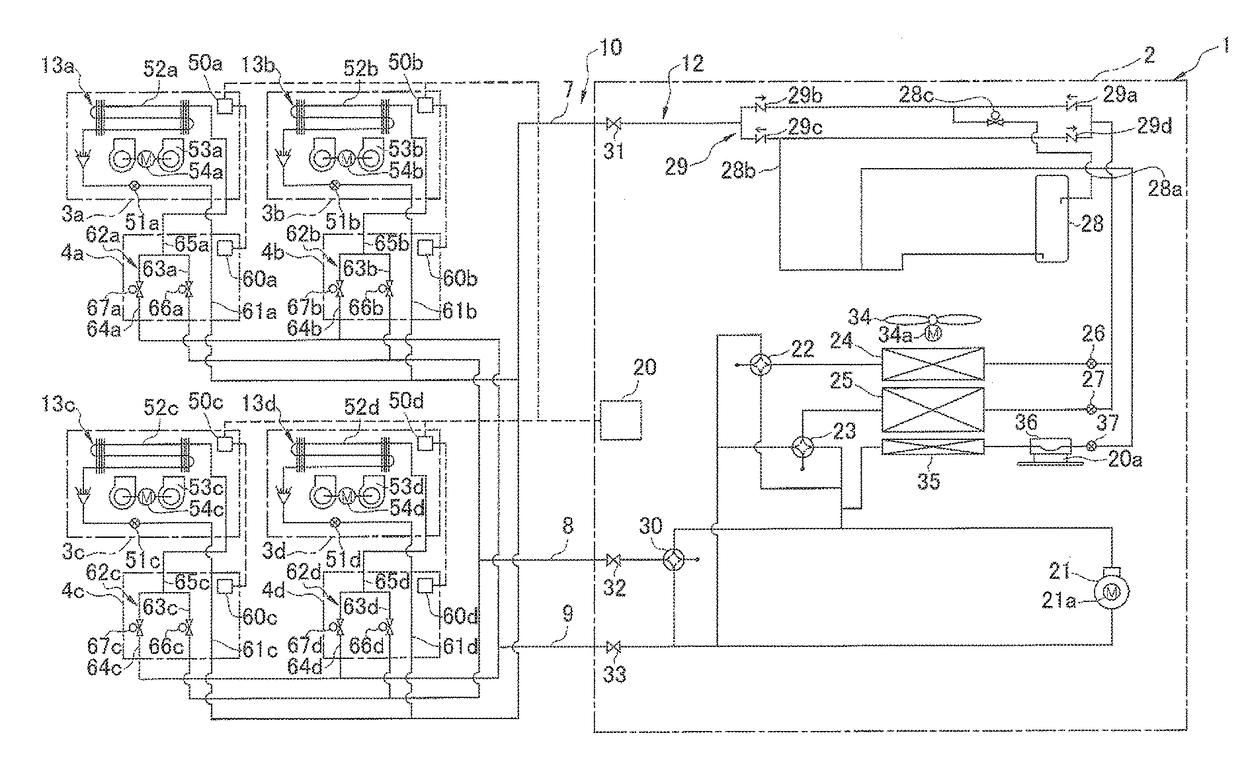
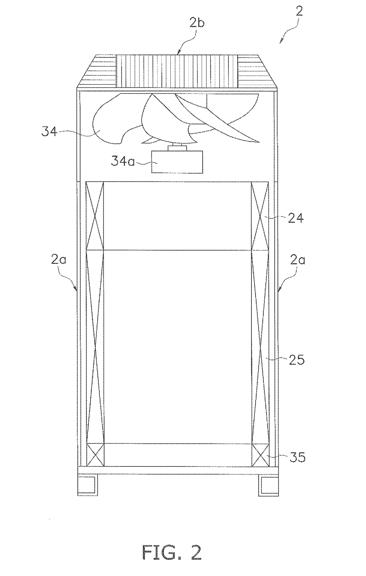
[0032]FIG. 1 is a schematic configuration diagram illustrating a simultaneous-cooling / heating-operation-type air conditioning apparatus 1 as an embodiment of the heat-recovery-type refrigerating apparatus according to the present invention. FIG. 2 is a view illustrating the general internal structure of a heat source unit 2 constituting the simultaneous-cooling / heating-operation-type air conditioning apparatus 1. FIG. 3...


PUM


Abstract

A heat-recovery-type refrigerating apparatus includes a compressor, a heat-source-side heat exchanger, and a plurality of usage-side heat exchangers, and refrigerant is sent from the usage-side heat exchanger functioning as a refrigerant radiator to the usage-side heat exchanger functioning as a refrigerant evaporator, whereby heat can be recovered between the usage-side heat exchangers. Here, a portion of the heat-source-side heat exchanger is configured as a precooling heat exchanger for always circulating high-pressure vapor refrigerant discharged from the compressor, and a refrigerant cooler for cooling an electrical equipment item is connected to a downstream side of the precooling heat exchanger.

Description

CROSS-REFERENCE TO RELATED APPLICATIONS[0001]This U.S. National stage application claims priority under 35 U.S.C. §119(a) to Japanese Patent Application No, 2013-210146, filed in Japan on Oct. 7, 2013, the entire contents of which are hereby incorporated herein by reference.TECHNICAL FIELD[0002]The present invention relates to a heat-recovery-type refrigerating apparatus, and relates particularly to a heat-recovery-type refrigerating apparatus which includes a compressor, a heat-source-side heat exchanger, and a plurality of usage-side heat exchangers, in which refrigerant is sent from the usage-side heat exchanger functioning as a refrigerant radiator to the usage-side heat exchanger functioning as a refrigerant evaporator, whereby heat can be recovered between the usage-side heat exchangers.BACKGROUND ART[0003]As disclosed in Japanese Laid-open Patent Application No. 2010-25374, a refrigerating apparatus is conventionally known in which a refrigerant cooler is provided for cooling...

Claims


Application Information

Patent Timeline
Patent Type & Authority Patents(United States)
IPC IPC(8): F25B27/00F25B13/00H05K7/20F25B39/02F25B31/00F25B49/02F25B6/02F25B40/02F25B5/02F25B41/00F25B41/04
CPCF25B13/00F25B31/006F25B39/028F25B49/02H05K7/20354F25B5/02F25B6/02F25B40/02F25B41/003F25B41/04F25B2313/007F25B2313/021F25B2313/0231F25B2313/0253F25B2313/02323F25B2600/2515F25B41/24
Inventor KAWANO, SATOSHITAKEUCHI, TOMOHISAKIMURA, SAYAKOMATSUOKA, SHINYA
Owner DAIKIN IND LTD
Why Eureka
Try Eureka