Expandable cardiac shunt

a shunt and expandable technology, applied in the field of expandable shunts, can solve the problems of increased end-diastolic pressure, few, if any, proven effective treatments, and symptomatic, and achieve the effect of facilitating collaps

Active Publication Date: 2017-10-17
EDWARDS LIFESCIENCES CORP
View PDF27 Cites 55 Cited by
  • Summary
  • Abstract
  • Description
  • Claims
  • Application Information

AI Technical Summary

Benefits of technology

[0009]Using catheter-based instruments, the surgeon creates a puncture hole between the left atrium and the coronary sinus, and places an expandable shunt within the puncture hole. A first puncture catheter having a side-extending needle may be used to form a puncture into the left atrium. A second delivery catheter extends along a guidewire and an expandable shunt with distal and proximal flanges is expelled therefrom into the puncture. The shunt defines a blood flow passage therethrough that permits shunting of blood from the left atrium to the coronary sinus when the LAP is elevated. The shunt is desirable formed of a super-elastic material and defines a tilted flow tube that facilitates collapse into the catheter.

Problems solved by technology

Heart failure is a common and potentially lethal condition affecting humans, with sub-optimal clinical outcomes often resulting in symptoms, morbidity and / or mortality, despite maximal medical treatment.
This condition is characterized by a stiff left ventricle with decreased compliance and impaired relaxation, which leads to increased end-diastolic pressure.
Approximately one third of patients with heart failure have diastolic heart failure and there are very few, if any, proven effective treatments.
In addition to diastolic heart failure, a number of other medical conditions, including systolic dysfunction of the left ventricle and valve disease, can lead to elevated pressures in the left atrium.
PH may arise from many different causes, but, in all patients, has been shown to increase mortality rate.
As a result, these small pulmonary arteries narrow and stiffen, causing blood flow to become restricted and upstream pressures to rise.

Method used


Image

  • Expandable cardiac shunt
  • Expandable cardiac shunt
  • Expandable cardiac shunt

Examples


Embodiment Construction

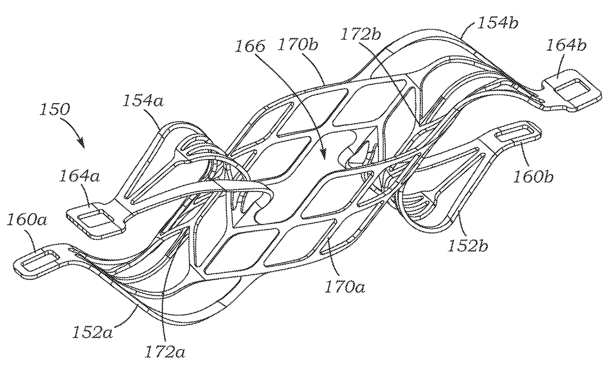
[0047]The present application discloses methods and devices that allow for elevated Left Atrial Pressure (LAP) to be reduced by shunting blood from the left atrium to the coronary sinus. The primary method includes implanting a shunt defining an open pathway between the left atrium and the coronary sinus, although the method can be used to place a shunt between other cardiac chambers, such as between the pulmonary artery and right atrium. The shunt is expandable so as to be compressed, delivered via a low profile sheath or tube, and expelled so as to resume its expanded state. The method also includes utilizing a deployment catheter that first creates a puncture in the wall between the left atrium and the coronary sinus. Details of these methods, implants and deployment systems will be described below.

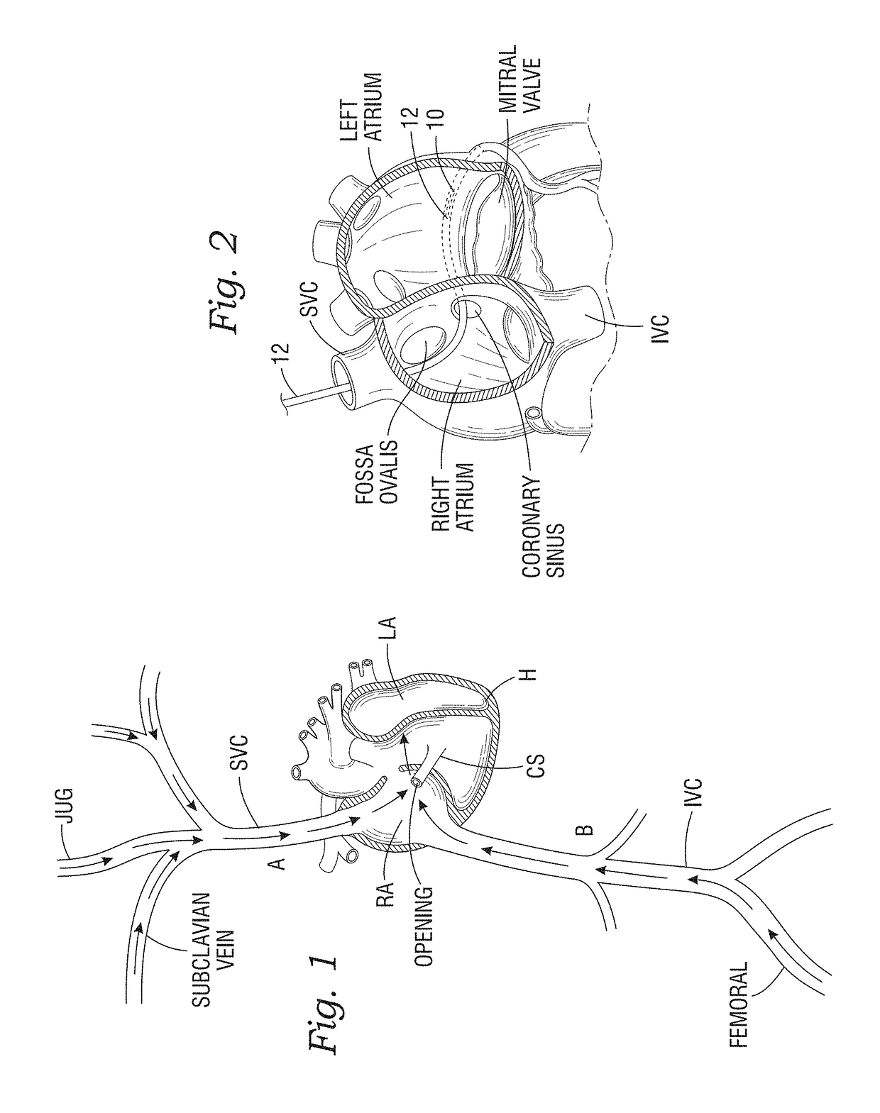
[0048]FIG. 1 illustrates several access pathways for maneuvering guidewires and catheters in and around the heart to deploy expandable shunts of the present application. For instance, ...


PUM


Abstract

Disclosed are cardiac shunts and method of delivery, and in particular, to a shunt to reduce elevated left atrial pressure (LAP). The methods include forming a puncture hole between the left atrium and the coronary sinus, widening the puncture hole, and placing an expandable shunt within the widened puncture hole. A first catheter having a side-extending needle may be used to form a puncture into the left atrium. A second catheter extends along a guidewire and an expandable shunt with distal and proximal flanges is expelled therefrom into the puncture. The shunt defines a blood flow passage therethrough that permits shunting of blood from the left atrium to the coronary sinus when the LAP is elevated. The shunt is desirable formed of a super-elastic material and manipulated with control rods. The shunt defines a tilted flow tube that facilitates collapse into the catheter.

Description

RELATED APPLICATIONS[0001]The present application claims priority under 35 U.S.C. 119 to both U.S. Provisional Application Ser. No. 62 / 262,052, filed Dec. 2, 2015 and U.S. Provisional Application Ser. No. 62 / 238,229, filed Oct. 7, 2015, the contents of which are expressly incorporated herein.FIELD OF THE INVENTION[0002]The present invention relates generally to cardiac shunts and systems and methods of delivery, and in particular, to a shunt to reduce left atrial pressure.BACKGROUND OF THE INVENTION[0003]In vertebrate animals, the heart is a hollow muscular organ having four pumping chambers: the left and right atria and the left and right ventricles, each provided with its own one-way valve. The natural heart valves are identified as the aortic, mitral (or bicuspid), tricuspid and pulmonary, and are each mounted in an annulus comprising dense fibrous rings attached either directly or indirectly to the atrial and ventricular muscle fibers. Each annulus defines a flow orifice. The fo...

Claims


Application Information

Patent Timeline
Patent Type & Authority Patents(United States)
IPC IPC(8): A61M27/00A61M25/01
CPCA61M27/008A61M25/0194A61M2025/0197A61M2205/0216A61M2210/125A61M25/007A61M25/0108A61M25/0113A61M25/04A61M25/06A61M25/1002A61M2025/0004A61M2025/0681A61M2025/1047A61M2205/32A61B17/11A61B17/3478A61B2017/00247A61B2017/00252A61B2017/1107A61B2017/1139A61B2017/22069A61B2090/3966A61B90/39A61B17/3403A61B17/3468A61M27/002
Inventor TAFT, ROBERT C.KARAPETIAN, EMILHERNANDEZ, CRISTOBAL R.
Owner EDWARDS LIFESCIENCES CORP
Why Eureka
Try Eureka