Waveguides with extended field of view

a waveguide and field of view technology, applied in the field of waveguides with extended field of view, can solve the problems of higher index of refraction and typically more expensiv

Active Publication Date: 2017-10-17
MICROSOFT TECH LICENSING LLC
View PDF51 Cites 52 Cited by
  • Summary
  • Abstract
  • Description
  • Claims
  • Application Information

AI Technical Summary

Benefits of technology

[0004]This Summary is provided to introduce a selection of concepts in a simplified form that are further described below in the Detailed Description. This Summary is not intended to identify key features or essential features of the claimed subject matter, nor is it intended to be used as an aid in determining the scope of the claimed subject matter.

Problems solved by technology

As this is still an emerging technology, there are certain challenges associated with utilizing waveguides to display images of virtual objects to a user.
This critical can be lowered slightly by using a reflective coating, or by using a material having a higher index of refraction, which is typically more expensive.

Method used


Image

  • Waveguides with extended field of view
  • Waveguides with extended field of view
  • Waveguides with extended field of view

Examples


Embodiment Construction

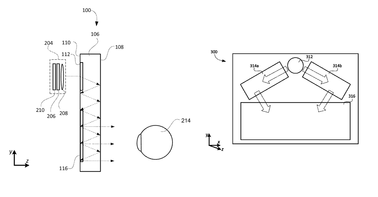
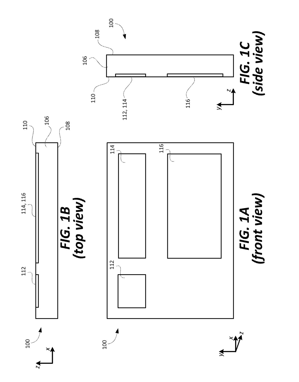
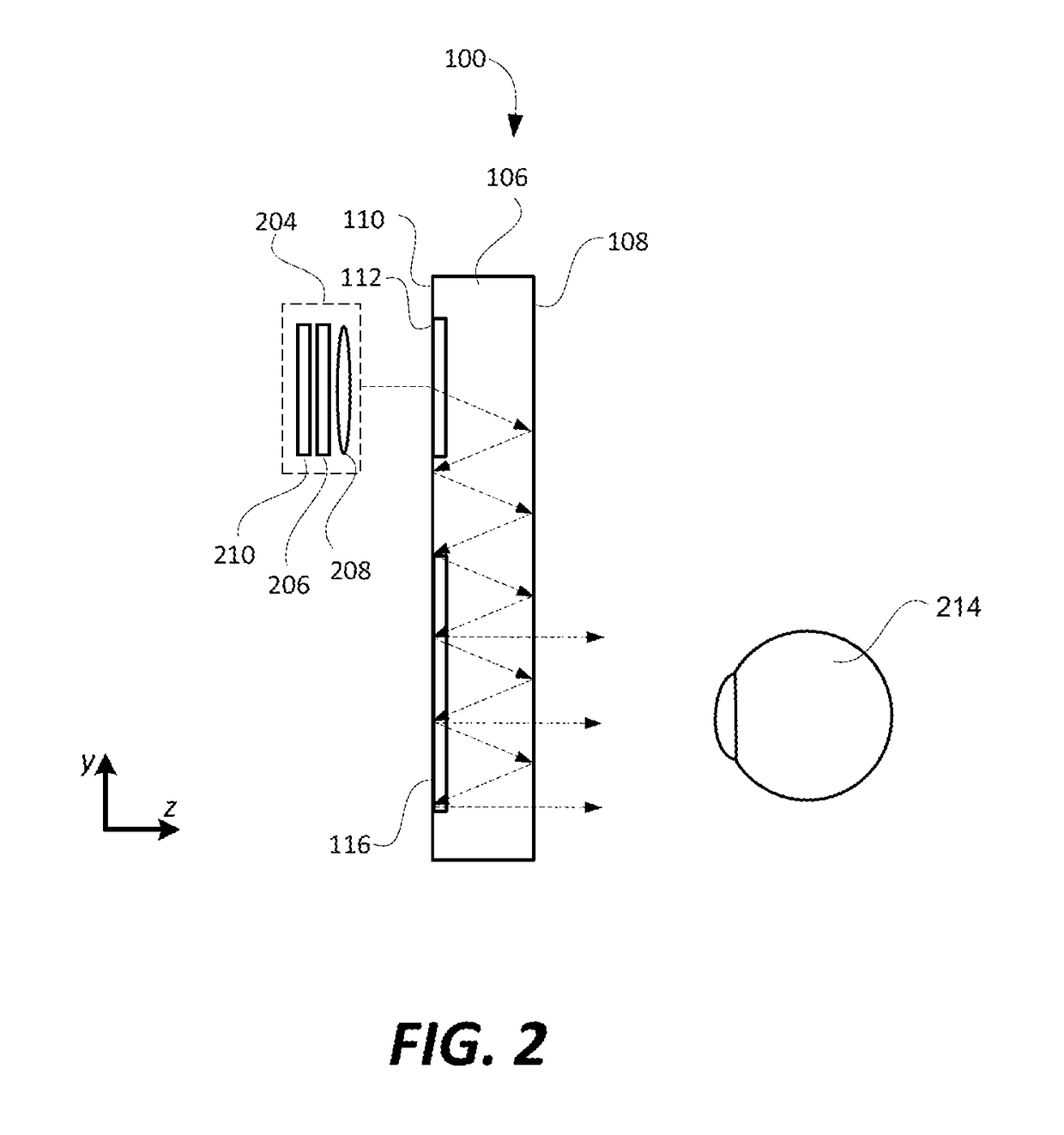
[0012]Certain embodiments of the present technology can be used to increase (also referred to as expand) the field of view (FOV) that can be supported by an optical waveguide that includes one or more intermediate-components that are used to perform pupil expansion, wherein the intermediate component(s) is / are typically what limit how large of a FOV can be supported by such an optical waveguide. Before providing details of such embodiments, FIGS. 1A, 1B and 1C are first used to describe an exemplary optical waveguide and its components, as well as its limitations. In the description that follows, like numerals or reference designators will be used to refer to like parts or elements throughout. In addition, the first digit of each reference number identifies the drawing in which the reference number first appears.

[0013]FIGS. 1A, 1B and 1C are front, top and side views, respectively, of an exemplary optical waveguide 100 that can be used to replicate an image associated with an input-...


PUM

PropertyMeasurementUnit
critical angleaaaaaaaaaa
internal anglesaaaaaaaaaa
anglesaaaaaaaaaa

Abstract

An input-coupler of an optical waveguide couples light corresponding to the image and having a corresponding FOV into the optical waveguide, and the input-coupler splits the FOV of the image coupled into the optical waveguide into first and second portions by diffracting a portion of the light corresponding to the image in a first direction toward a first intermediate-component, and diffracting a portion of the light corresponding to the image in a second direction toward a second intermediate-component. An output-coupler of the waveguide combines the light corresponding to the first and second portions of the FOV, and couples the light corresponding to the combined first and second portions of the FOV out of the optical waveguide so that the light corresponding to the image and the combined first and second portions of the FOV is output from the optical waveguide. The intermediate-components and the output-coupler also provide for pupil expansion.

Description

BACKGROUND[0001]Various types of computing, entertainment, and / or mobile devices can be implemented with a transparent or semi-transparent display through which a user of a device can view the surrounding environment. Such devices, which can be referred to as see-through, mixed reality display device systems, or as augmented reality (AR) systems, enable a user to see through the transparent or semi-transparent display of a device to view the surrounding environment, and also see images of virtual objects (e.g., text, graphics, video, etc.) that are generated for display to appear as a part of, and / or overlaid upon, the surrounding environment. These devices, which can be implemented as head-mounted display (HMD) glasses or other wearable display devices, but are not limited thereto, often utilize optical waveguides to replicate an image, e.g., produced by a display engine, to a location where a user of a device can view the image as a virtual image in an augmented reality environmen...

Claims


Application Information

Patent Timeline
Patent Type & Authority Patents(United States)
IPC IPC(8): G02B27/14G02B27/01F21V8/00G02B27/44G02B5/18G02F1/29G02F1/295G02B27/22G02B27/00H04N13/04G02B27/42
CPCG02B27/0172G02B5/1814G02B6/005G02B27/0081G02B5/1819G02B27/2235H04N13/0429G02B27/44G02F1/292H04N13/044G02F1/295G02B6/0026G02B2027/0125G02B2027/013G02B5/18G02B2005/1804G02B27/4205G02B2027/0174G02B2027/0123H04N13/332H04N13/344G02B30/35
Inventor VALLIUS, TUOMASTERVO, JANI
Owner MICROSOFT TECH LICENSING LLC
Why Eureka
Try Eureka