Insulating protrusion in the trench of a re-distribution layer structure

Active Publication Date: 2017-10-17
CHIPMOS TECH INC
View PDF5 Cites 1 Cited by
  • Summary
  • Abstract
  • Description
  • Claims
  • Application Information

AI Technical Summary

Benefits of technology

[0006]The invention is directed to a re-distribution layer structure, w

Problems solved by technology

However, the thin and narrow type wire also reduces an area for adhesion between itself and the underlying substrate or

Method used


Image

  • Insulating protrusion in the trench of a re-distribution layer structure
  • Insulating protrusion in the trench of a re-distribution layer structure
  • Insulating protrusion in the trench of a re-distribution layer structure

Examples


Example

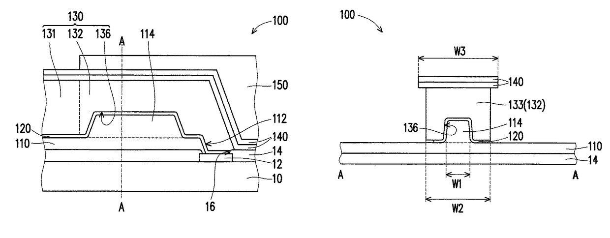
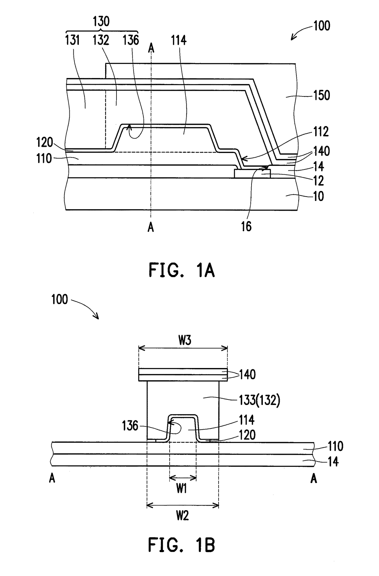
[0030]FIG. 1A is a schematic partial cross-sectional view illustrating a re-distribution layer structure according to an embedment of the invention. Referring to FIG. 1A, in the present embodiment, a re-distribution layer structure 100 adapted to be disposed on a substrate 10 to re-distribute a pad 12 of the substrate 10 to other position. In the present embodiment, the substrate 10 may be a circuit board, a wafer or a chip, and the type of the substrate 10 is not limited thereto. As shown in FIG. 1A, the substrate 10 has a pad 12 and a protective layer 14, wherein the protective layer 14 has a first opening 16, and the first opening 16 exposes a part of the pad 12.

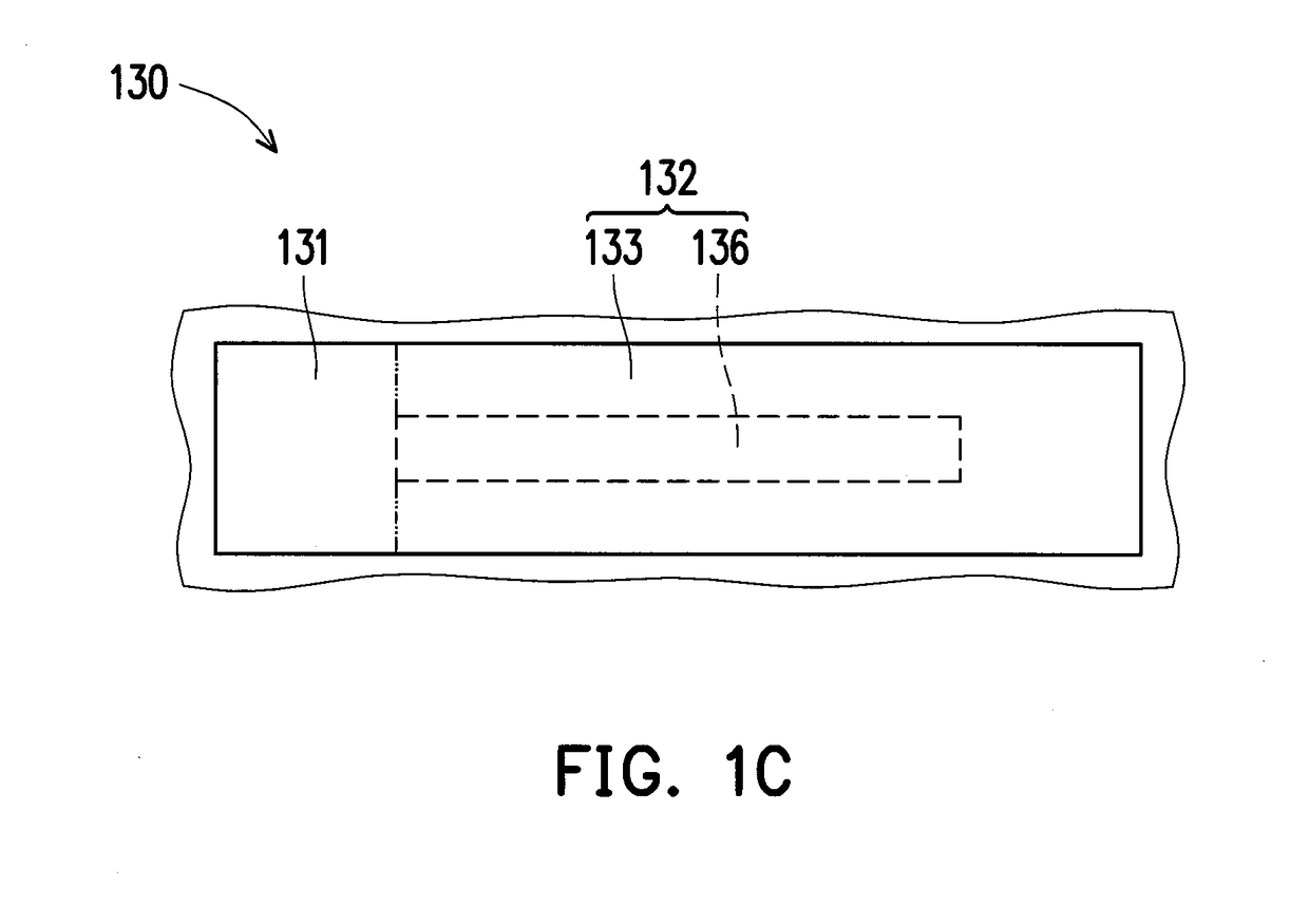
[0031]The re-distribution layer structure 100 includes a first patterned insulating layer 110, a re-distribution layer 130 and a second patterned insulating layer 150. The first patterned insulating layer 110 is disposed on the protective layer 14 and includes a second opening 112, wherein the second opening 112 is corres...


PUM


Abstract

A re-distribution layer structure is adapted to be disposed on a substrate having a pad and a protective layer which has a first opening exposing a part of the pad. The re-distribution layer structure includes a first and a second patterned insulating layers and a re-distribution layer. The first patterned insulating layer is disposed on the protective layer and includes at least one protrusion and a second opening corresponding to the first opening. The re-distribution layer is disposed on the first patterned insulating layer and includes a pad portion and a wire portion. The pad portion is located on the first patterned insulating layer. The wire portion includes a body and at least one trench caved in the body. The body extends from the pad portion to the pad exposed by the first and the second openings. The body covers the protrusion, and the at least one protrusion extends into the at least one trench. The second patterned insulating layer covers the wire portion and exposes a part of the pad portion. A manufacturing method of re-distribution layer structure is further provided.

Description

CROSS-REFERENCE TO RELATED APPLICATION[0001]This application claims the priority benefit of Taiwan application serial no. 105138518, filed on Nov. 23, 2016. The entirety of the above-mentioned patent application is hereby incorporated by reference herein and made a part of this specification.BACKGROUND OF THE INVENTION1. Field of the Invention[0002]The invention generally relates to a circuit structure and a manufacturing method thereof, and more particularly, to a re-distribution layer structure and a manufacturing method thereof.2. Description of Related Art[0003]In modern time, the multimedia application market is expanding quickly. The packaging technique of integrated circuits must be developed to meet the development of such electronic devices. In order to achieve the above requirements, it is necessary to strengthen the features of high-speed processing, multifunction, integration, small scale and light-weight, low price, etc. of the electronic devices. Accordingly, the devel...

Claims


Application Information

Patent Timeline
IPC IPC(8): H01L23/12H01L23/48H01L21/48H01L21/768H01L21/00H01L23/00
CPCH01L24/05H01L21/76898H01L24/11H01L21/76802H01L21/76877H01L21/4846H01L23/481H01L24/19H01L24/03H01L2224/02206H01L2224/04042H01L2224/0233H01L2224/0235H01L2224/0401H01L2224/4805H01L2224/02317H01L2224/05027H01L24/02H01L2224/0231H01L2224/02373H01L2224/02331H01L2224/0237H01L2224/0236H01L23/525H01L2924/00014H01L23/3192H01L2224/02351H01L2224/02375H01L24/13
Inventor HU, EN-SUNG
Owner CHIPMOS TECH INC
Why Eureka
Try Eureka