Plate with printing layer and display device using the same

Active Publication Date: 2017-05-18
ASAHI GLASS CO LTD
View PDF0 Cites 2 Cited by
  • Summary
  • Abstract
  • Description
  • Claims
  • Application Information

AI Technical Summary

Benefits of technology

The present invention relates to a plate used in printing, where the surface roughness of the outer circumferential region of the plate is larger than the inner circumferential region. This surface roughness causes the ink used in printing to incorporate into the surface structure, making it difficult for the printing layer to peel off the plate. As a result, plates with less defects can be prepared. Additionally, the invention provides a display device with the same plate used for printing, which helps to prevent peeling and cracking of the printing layer.

Problems solved by technology

As a result, the printing layer is difficult to peel, and a plate with a printing layer having less defects can be prepared.

Method used


Image

  • Plate with printing layer and display device using the same
  • Plate with printing layer and display device using the same
  • Plate with printing layer and display device using the same

Examples


first embodiment

[0044](Structure of Plate with Printing Layer)

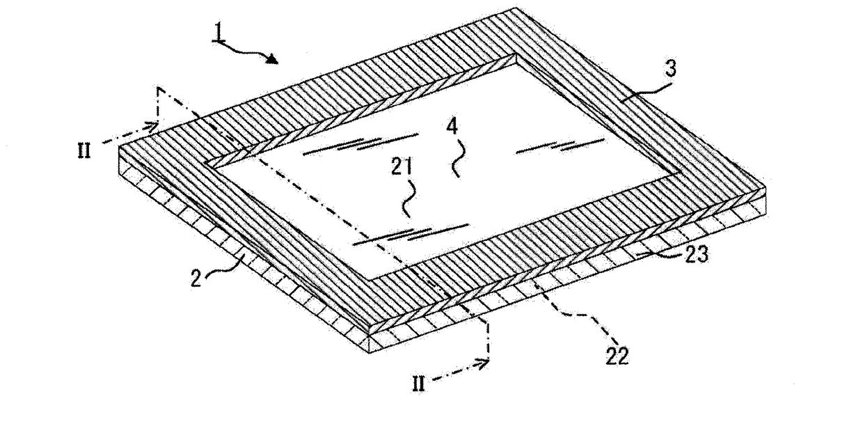
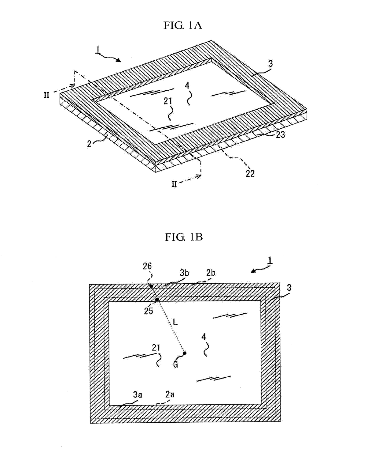
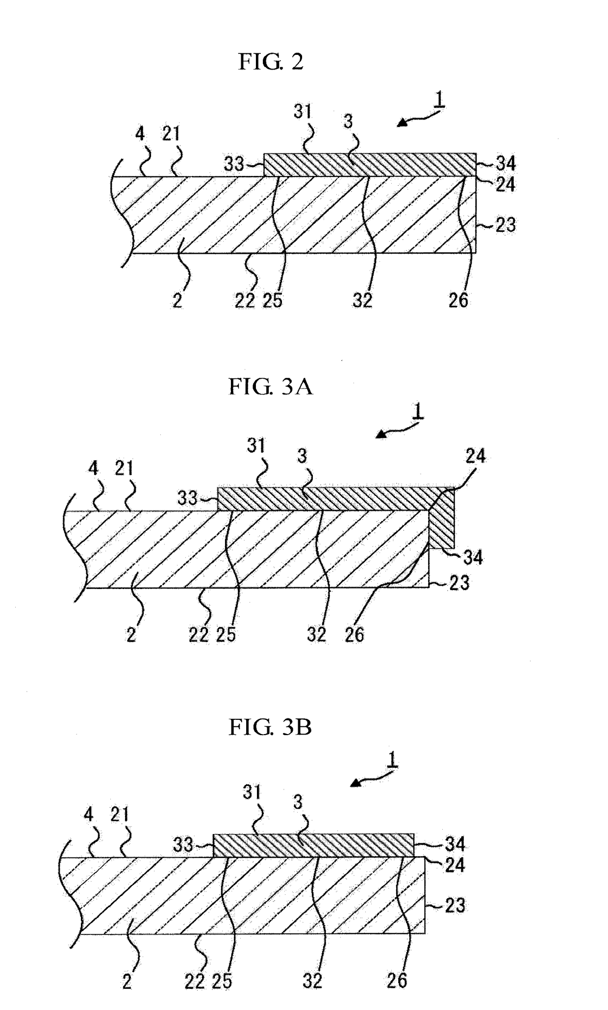
[0045]FIG. 1A and FIG. 1B are a perspective view and a plan view, respectively, which illustrate the whole structure of a plate with a printing layer according to a first embodiment of the present invention. FIG. 2 is a cross-sectional view taken along II-II in FIG. 1A. A plate 1 with a printing layer of the present embodiment contains a plate 2 and a printing layer 3.

[0046]The plate 2 has a first main surface 21, a second main surface 22 and an edge face 23.

[0047]The printing layer 3 is provided on a periphery of the first main surface 21 of the plate 2, and is formed by recoating to form plural layers such that a function such as a desired light-shielding property is achieved. A region other than the printing layer 3 on the plate 2 constitutes a display region 4. The printing layer 3 has a face 31 that does not come in contact with the plate 2, a face 32 that comes in contact with the plate 2, an inner circumferential edge 33 that is a...

second embodiment

[0058](Plate with Printing Layer Having Connection Part 24 of Arc-Shaped Cross-Section)

[0059]The second embodiment is the same as the first embodiment, except for the shape of the connection part 24. In the description of the second embodiment, the same structure as the first embodiment is denoted by the same reference numeral and sign, and the explanation thereof is omitted.

[0060]FIG. 4A, FIG. 4B and FIG. 4C illustrate cross-sectional views of the plates 1 with a printing layer according to the second embodiment. In the second embodiment, the connection part 24 has an arc-shaped cross-section that is a curved surface having a center of curvature inside the plate 2 and having a radius of curvature of 0.05 mm or more and 0.5 mm or less. The radius of curvature is preferably 0.05 mm or more and 0.4 mm or less, and more preferably 0.05 mm or more and 0.3 mm or less. Accordingly, an impact caused at the time of factory shipment and product assembly disperses without concentrating in one...

third embodiment

[0063](Plate with Printing Layer Having Connection Part 24 of Cross-Sectional Line Segment Shape)

[0064]The third embodiment is the same as the first embodiment, except for the shape of the connection part 24. In the description of the third embodiment, the same structure as the first embodiment is denoted by the same reference numeral and sign, and the explanation thereof is omitted.

[0065]FIG. 5A, FIG. 5B and FIG. 5C illustrate cross-sectional views of the plates 1 with a printing layer according to the third embodiment. In the third embodiment, the connection part 24 constitutes a line segment connecting a side corresponding to the first main surface 21 or the second main surface 22 and a side corresponding to the edge face 23 in a cross-sectional view in a thickness direction. The angle at a plate side formed at the intersection point between one of the sides corresponding to the first main surface 21 and the second main surface 22 and the line segment, and the angle at a plate si...


PUM

PropertyMeasurementUnit
Angleaaaaaaaaaa
Lengthaaaaaaaaaa
Lengthaaaaaaaaaa

Abstract

The present invention relates to a plate with a printing layer containing a plate having a first main surface, a second main surface and an edge face, and a printing layer provided on a periphery of the first main surface, in which the plate has an outer circumferential part corresponding to an outer circumferential part of the printing layer and an inner circumferential part corresponding to an inner circumferential part of the printing layer, in which the outer circumferential part of the plate has, in at least a part of the whole circumference, an outer circumferential region, and the inner circumferential part of the plate contains an inner circumferential region corresponding to the outer circumferential region, and in which the outer circumferential region has a surface roughness R2 and the inner circumferential region has a surface roughness R1, and R2>R1 is satisfied.

Description

TECHNICAL FIELD[0001]The present invention relates to a plate with a printing layer and a display device using the same.BACKGROUND ART[0002]A display device such as a liquid crystal display device is conventionally used in a personal digital assistance such as a mobile phone, and in a panel display. Those display devices are composed of a display panel such as a liquid crystal panel displaying an image, a backlight emitting illumination light to the display panel, and the like. In recent years, a protective member has been arranged on a front surface of these display panels in order to reduce external light reflection and to protect the display panel from external shock.[0003]At first, illumination light from the backlight has leaked outside the display panel in some cases, and the illumination light leaked has leaked to a user side in some cases from a space between the display panel and a case housing the same. There has been a problem that the leaked illumination light makes it d...

Claims


Application Information

Patent Timeline
IPC IPC(8): B32B7/02B32B17/06B32B7/12
CPCB32B2457/202B32B17/06B32B7/12B32B7/02B32B17/00B32B27/08B32B3/08B32B2250/24B32B2255/10B32B2255/20B32B2255/26B32B2255/28B32B2307/4023B32B2307/412B32B2307/418B32B2307/50B32B2307/538B32B2307/732B32B2307/75B32B2457/20
Inventor KOBUNE, SHINJIKOYAMA, KEIKO
Owner ASAHI GLASS CO LTD
Why Eureka
Try Eureka