Carrier with lowered platform height

a technology of platform height and carrier, which is applied in the direction of load transportation vehicles, transportation items, transportation vehicles, etc., can solve the problem that none of these prior art patents relate specifically to the objective of lowering the platform height, and achieve the effect of minimizing the height of the platform surface and no wasted spa

Inactive Publication Date: 2017-10-24
LAGANAS STEVEN +1
View PDF15 Cites 20 Cited by
  • Summary
  • Abstract
  • Description
  • Claims
  • Application Information

AI Technical Summary

Benefits of technology

[0009]The sub frame rails are wider than the top surface of the chassis frame; they are aligned so that their inner edge is aligned with the inner edge of the chassis frame members and their outer edges overhang by a few inches. A lifting bracket is welded to the underside of each sub frame rail underneath the overhang and adjacent to the chassis frame to accept the end of a lifting cylinder rod while leaving some space for sliding engagement of a platform beam whi...

Problems solved by technology

None of these prior art patents relate specific...

Method used


Image

  • Carrier with lowered platform height
  • Carrier with lowered platform height
  • Carrier with lowered platform height

Examples


Embodiment Construction

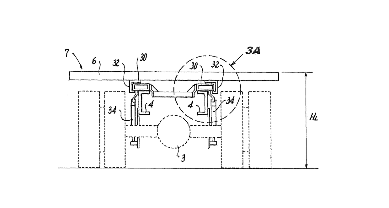
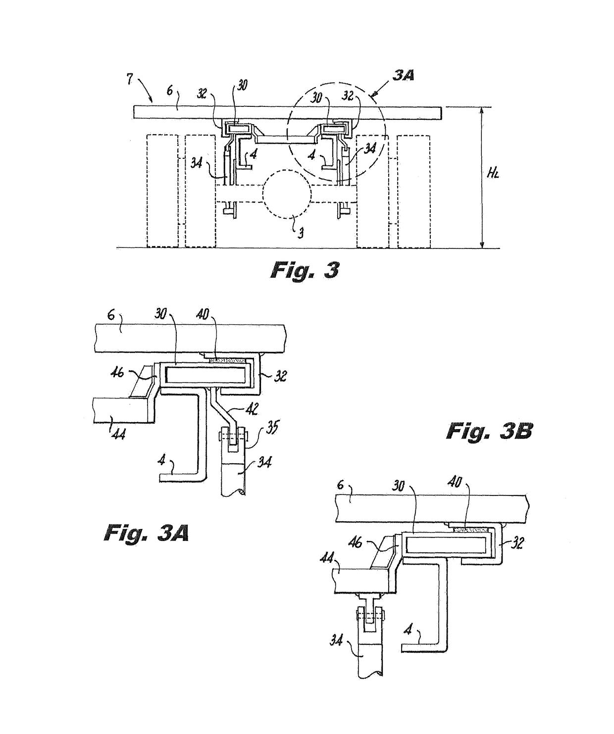
[0027]The salient features dictating differences in platform height and means by which they are achieved is illustrated by the various figures that follow. Obvious means such as attempts to use smaller wheels or high strength steel to reduce platform thickness or height of carrier chassis side frame members will not be discussed as the economics dictate that the starting point for such vehicle carriers as these is a “standard” flatbed truck chassis as supplied by a major manufacturer.

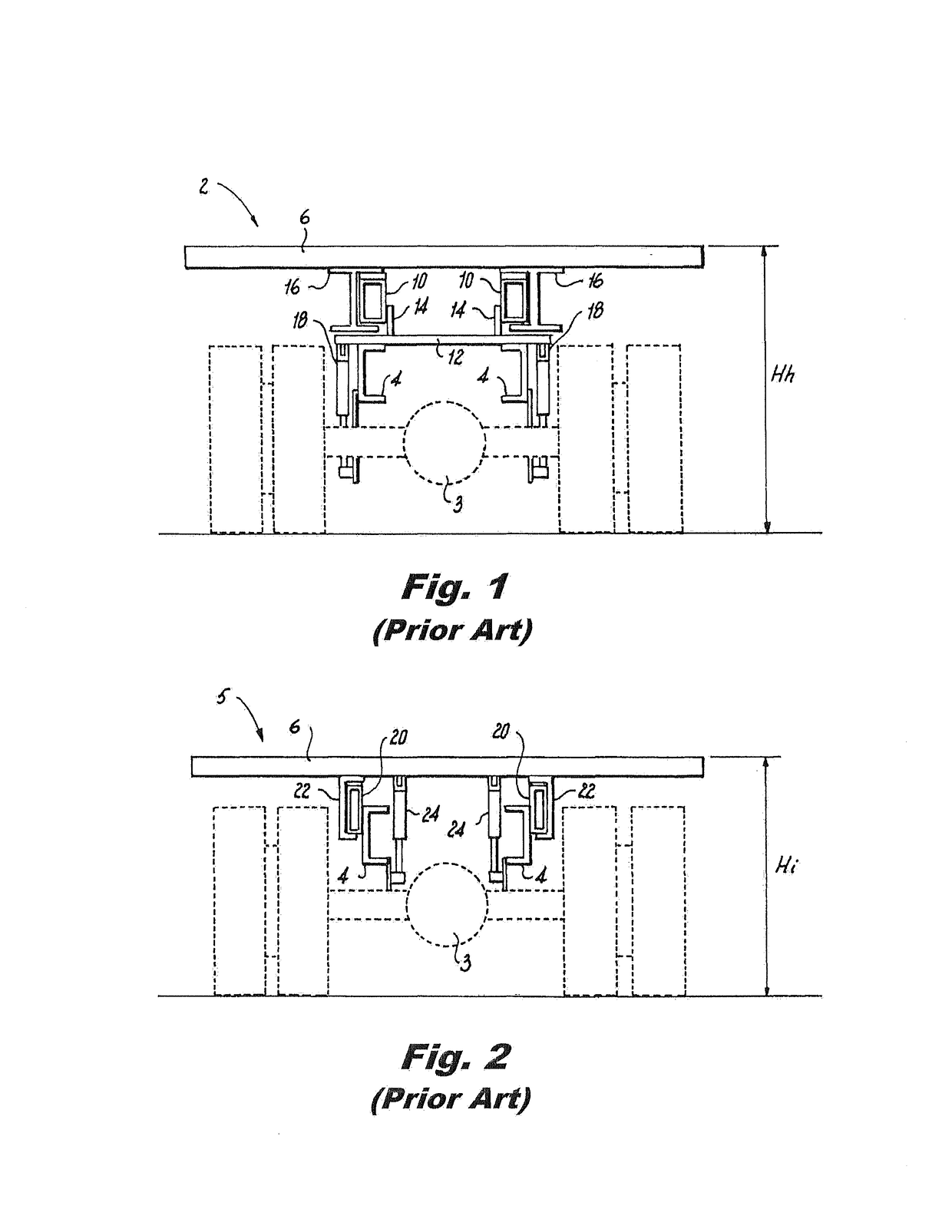
[0028]FIGS. 1-3 compare the differences in structural elements used in two prior art carriers as compared and contrasted with those of the present invention. These are mere rear view schematic illustrations leaving out essential items such as cross members tying together sub frame rails to clarify the images of elements directly involved in platform height determination. The same truck chassis with rear axle 3 and side frame members 4 is assumed in each case.

[0029]FIG. 1 shows a prior art carrier 2 usin...


PUM


Abstract

A tow truck carrier with sub frame rails above the carrier chassis frame rails that also reduces platform height thereby presenting a lower center of gravity. Sub frame rails of rectangular steel tubing with the wider dimension of the tubing are used in a horizontal, low profile orientation, with the direct attachment of the lift cylinder ends to the sub frame rails or to a cross beam to lower the platform. The sub frame rails form a descending ladder frame with cross members attached via brackets so that they are lowered into the recess between the chassis side frame. A lifting bracket is welded to the underside of each sub frame rail underneath the overhang and adjacent to the chassis frame to accept the end of a lifting cylinder rod while leaving some space for sliding engagement of a platform beam which engages three edges of the sub frame rail.

Description

FIELD OF THE INVENTION[0001]The present invention relates to tow truck carriers with lowered platform height and lower center of gravity.BACKGROUND OF THE INVENTION[0002]The present invention relates to tilting platform carriers in which the platform also slides in relation to the vehicle frame. These carriers are most often used to pick up and carry disabled vehicles transporting them to repair centers; they may also be used to transport industrial and agricultural equipment.[0003]The basic motion of the platform relative to the truck frame is well illustrated in U.S. Pat. No. 3,485,400 of Pewthers. FIGS. 1-3 show the sequence of starting with the platform in a horizontal forward transporting position, to sliding the platform rearward, and finally raising the front of the platform with a hydraulic cylinder pivoting its distal overhanging end to ground contact. While these basic moves do not equate to modern carriers with additional disabled vehicle handling equipment, other patents...

Claims


Application Information

Patent Timeline
IPC IPC(8): B60P1/30B60P3/12B60P3/07
CPCB60P1/30B60P3/07B60P3/122B60P1/32
Inventor NOLASCO, PABLO
Owner LAGANAS STEVEN
Why Eureka
Try Eureka