Interferometer having two transparent plates in parallel for making reference and measurement beams parallel

a technology of parallel reference and measurement beams, applied in the field of interferometers, can solve the problems that the polarization beam-splitter cube and the triple prism can only be produced with great expense, and the mounting of these components is necessary for very costly and low-drift. to achieve the effect of simple production

Active Publication Date: 2017-10-24
DR JOHANNES HEIDENHAIN GMBH
View PDF17 Cites 0 Cited by
  • Summary
  • Abstract
  • Description
  • Claims
  • Application Information

AI Technical Summary

Benefits of technology

[0006]Example embodiments of the present invention provide a compactly constructed interferometer that has optical components which are as simple to produce as possible.
[0023]the second and fourth imaging optical systems reducing the beam diameter of the beam of rays falling on them to the entrance-beam diameter.
[0049]the second and fourth imaging optical systems reducing the beam diameter of the beam of rays falling on them to the entrance-beam diameter.
[0076]According to example embodiments of the present invention, costly production of a beam-splitter cube and one or more triple prisms may be eliminated. Furthermore, according to example embodiments of the present invention, only plane-parallel plates, on which suitable optical elements are disposed, may be necessary to implement the optical functionality of a beam-splitter cube and triple prisms in the beam paths. Such plane-parallel plates, including the elements on them, may be produced simply and inexpensively using suitable lithography processes. In particular, the troublesome polishing of 90° angles may no longer be necessary. The adhesives in optically relevant areas of the beam paths necessary in conventional systems or the wringing of optical elements may also be omitted. Moreover, the painstaking, low-drift positioning of optical components in the beam paths may also no longer be necessary.

Problems solved by technology

It is considered to be disadvantageous with regard to such interferometers that both the polarization beam-splitter cube and the triple prism can only be produced with great expense.
In the case of the spatially separate placement of beam-splitter cube and triple prisms, a likewise very costly low-drift mounting of these components is necessary.

Method used


Image

  • Interferometer having two transparent plates in parallel for making reference and measurement beams parallel
  • Interferometer having two transparent plates in parallel for making reference and measurement beams parallel
  • Interferometer having two transparent plates in parallel for making reference and measurement beams parallel

Examples


Embodiment Construction

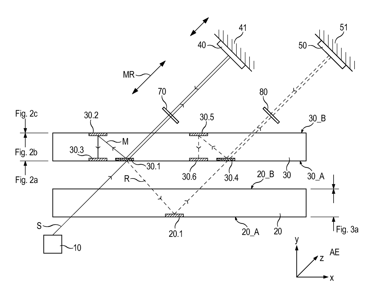
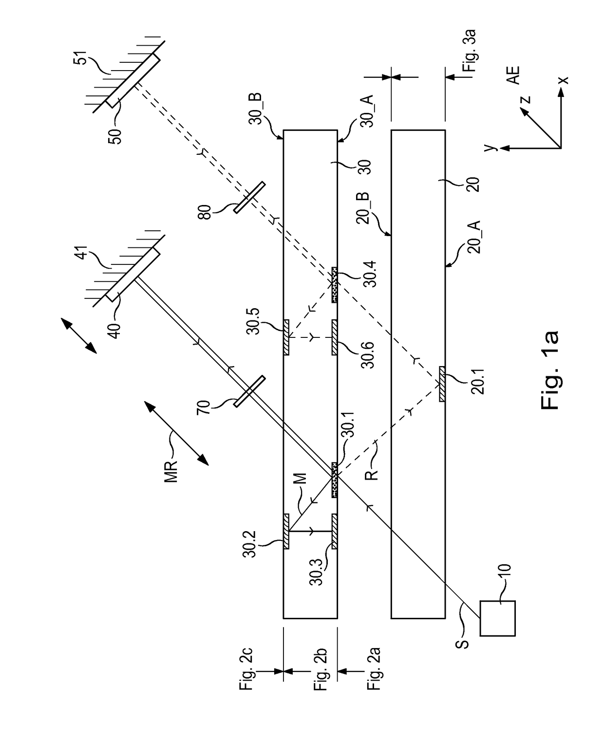
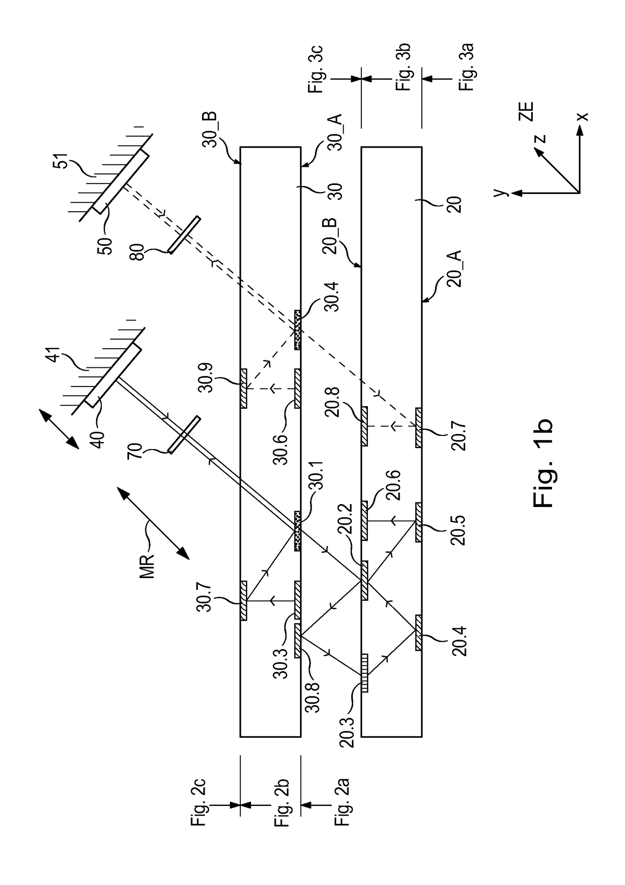
[0091]An interferometer according to a first example embodiment of the present invention is described below with reference to FIG. 1a to 1d, 2a to 2c, and 3a to 3c. FIGS. 1a to 1d are different views of the beam path, and FIGS. 2a to 2c and 3a to 3c are plan views of different sides of the plane-parallel plates used, having the optical elements disposed on them.

[0092]The interferometer includes at least one light source 10, a first beam splitter 30.1, a measuring reflector 40, a reference reflector 50, a detection unit 60, and at least two transparent plane-parallel plates 20, 30. Lower plane-parallel plate 20 in each of FIGS. 1a to 1c is referred to hereinafter as first plane-parallel plate 20, and upper plane-parallel plate 30 is referred to as second plane-parallel plate. The two plane-parallel plates 20, 30, which are produced from a suitable glass material, for example, are disposed parallel to one another at a specific distance in the beam path between light source 10 and dete...


PUM


Abstract

An interferometer includes a light source, a beam splitter, a reference reflector, a measuring reflector, a detection unit, and at least two transparent plane-parallel plates. The beam splitter splits a beam of rays into at least one measuring beam and at least one reference beam. Until being recombined, the measuring beam propagates in a measuring arm, and the reference beam propagates in a reference arm. The reference beam falls at least three times on the reference reflector located in the reference arm. The measuring reflector is disposed in the measuring arm and is joined to an object to be measured, which is movable along a measuring direction relative to the reference reflector. The measuring beam falls at least three times on the measuring reflector. At least one distance signal with regard to the position of the object to be measured is ascertainable from the interfering measuring and reference beams via the detection unit. The plane-parallel plates are disposed parallel to each other in the beam path between the light source and the detection unit. At least the measuring reflector is movable relative to the plane-parallel plates along the measuring direction. The plane-parallel plates each include a plurality of optical elements that exert such an optical effect on the measuring beam and the reference beam that they propagate parallel to each other in the direction of the measuring reflector and reference reflector, respectively.

Description

CROSS-REFERENCE TO RELATED APPLICATIONS[0001]The present application claims priority to application No. 10 2014 214 839.1, filed in the Federal Republic of Germany on Jul. 29, 2014, which is expressly incorporated herein in its entirety by reference thereto.FIELD OF THE INVENTION[0002]The present invention relates to an interferometer, for example, that is particularly suitable for the high-precision measurement of length and / or distance.BACKGROUND INFORMATION[0003]A so-called plane-mirror interferometer is described, for example, in U.S. Pat. No. 4,752,133. It includes a light source, a first beam splitter, and a detection unit. A beam of rays emitted by the light source is split via the first beam splitter into at least one measuring beam and at least one reference beam. The measuring beam and the reference beam then propagate in a measuring arm and in a reference arm, respectively, until they are recombined at the beam splitter. In the measuring arm, a measuring reflector in the ...

Claims


Application Information

Patent Timeline
Patent Type & Authority Patents(United States)
IPC IPC(8): G01B9/08G01B9/02G01B11/14
CPCG01B9/02015G01B9/02018G01B11/14G01B9/02061G01B2290/70G01B9/02057
Inventor MEISSNER, MARKUS
Owner DR JOHANNES HEIDENHAIN GMBH
Why Eureka
Try Eureka