Method for laterally moving industrial machine

a technology for industrial machines and lateral moving, which is applied in the direction of machines/engines, machine supports, lifting equipment, etc., can solve the problems of inability to remove the generator field axially, inability to lift the machine, and inability to maintain other industrial machines with similar clearance limitations

Active Publication Date: 2017-10-31
GE INFRASTRUCTURE TECH INT LLC
View PDF29 Cites 127 Cited by
  • Summary
  • Abstract
  • Description
  • Claims
  • Application Information

AI Technical Summary

Problems solved by technology

In terms of the generator example, with the three main rotating components of the single shaft combined-cycle system secured to the foundation, and in axial alignment one with the other parts, it is not possible to remove the generator field axially due to the lack of clearance with respect to the turbines at opposite ends of the generator.
However, because the generator is an electromagnetic generator, it is not typically possible to split the generator rotor and casing at the centerline and lift the generator rotor from the generator in a vertical direction.
Similar clearance limitations plague maintenance of other industrial machines.
Often it is necessary to bring in specialized heavy-duty lifting equipment for these lifts as on-site lift capability is usually inadequate to perform such lifts.

Method used


Image

  • Method for laterally moving industrial machine
  • Method for laterally moving industrial machine
  • Method for laterally moving industrial machine

Examples


Embodiment Construction

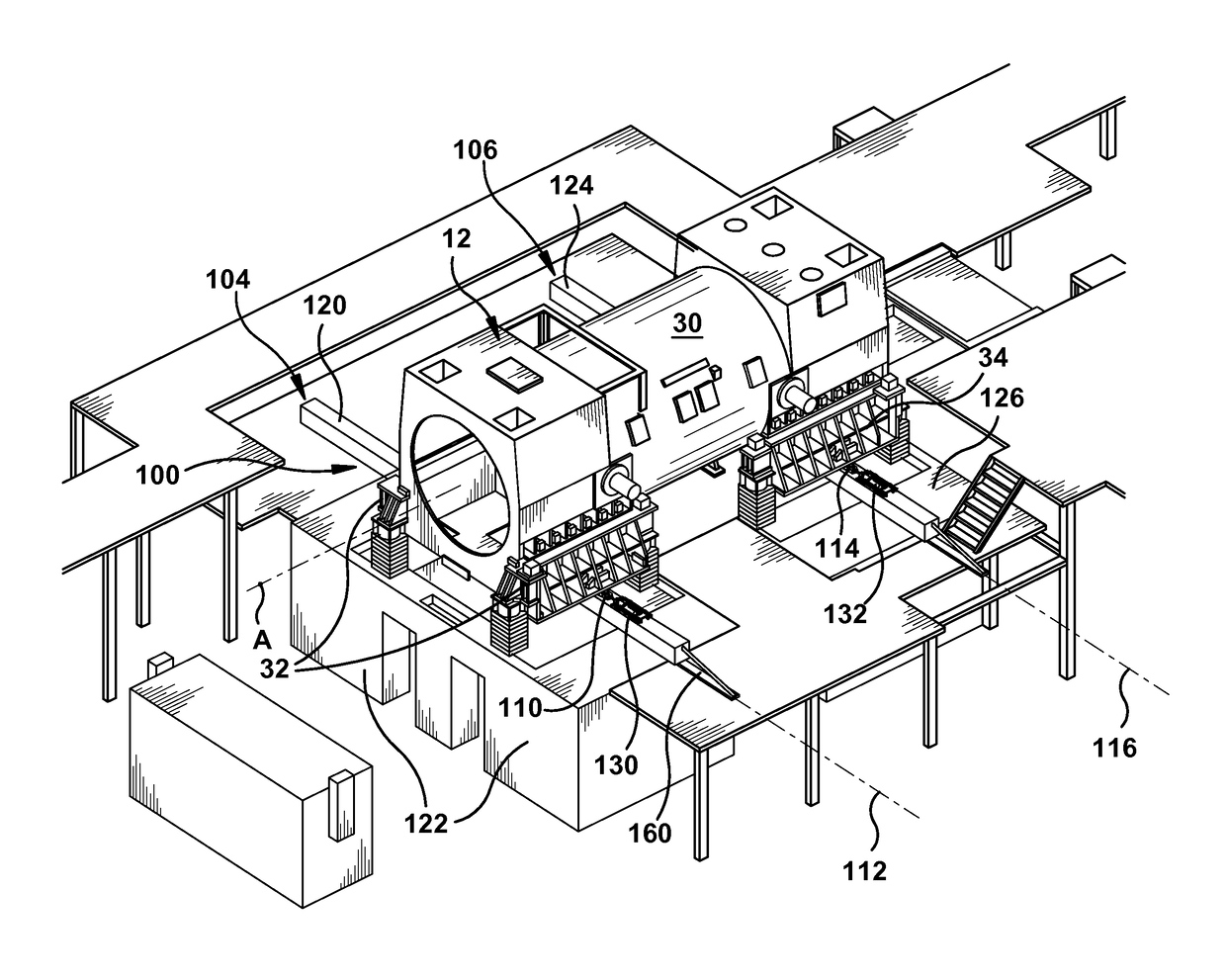
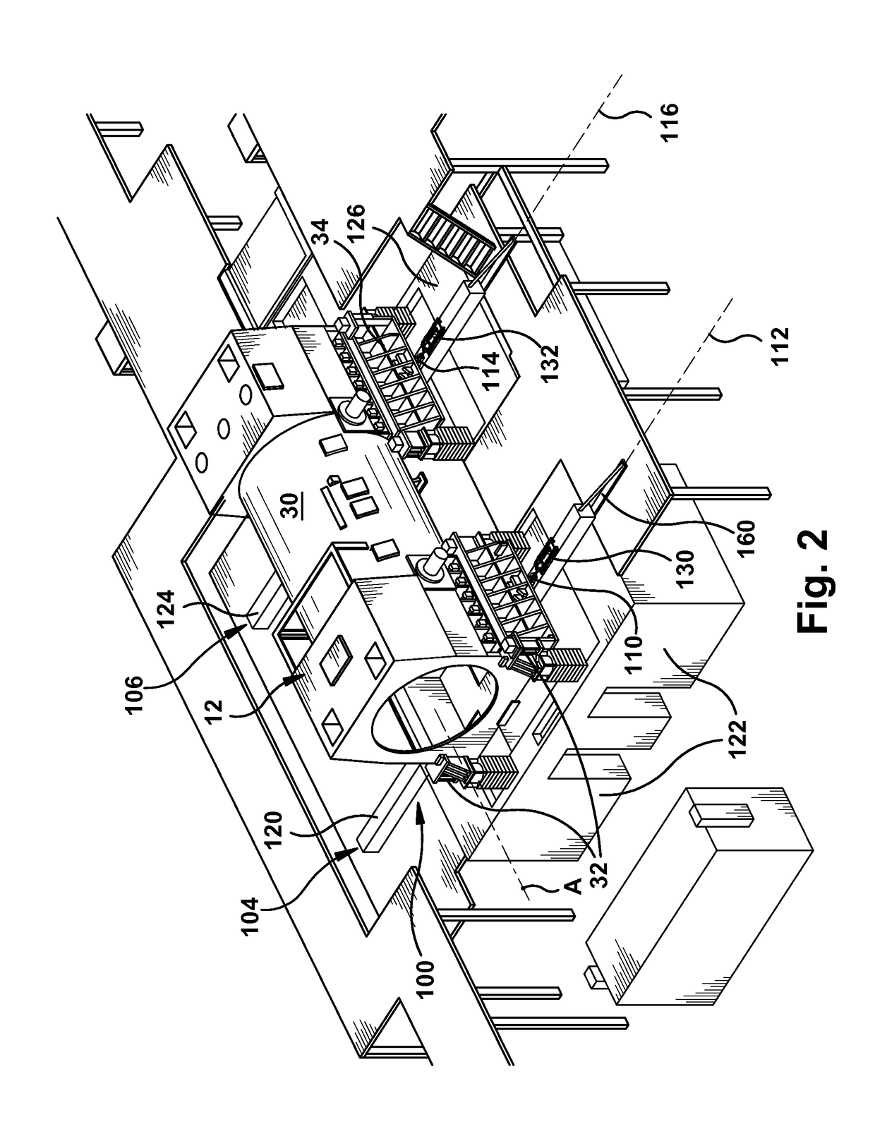
[0052]As indicated above, the disclosure provides a system and method for laterally moving an industrial machine, such as a generator in a power plant, for maintenance.

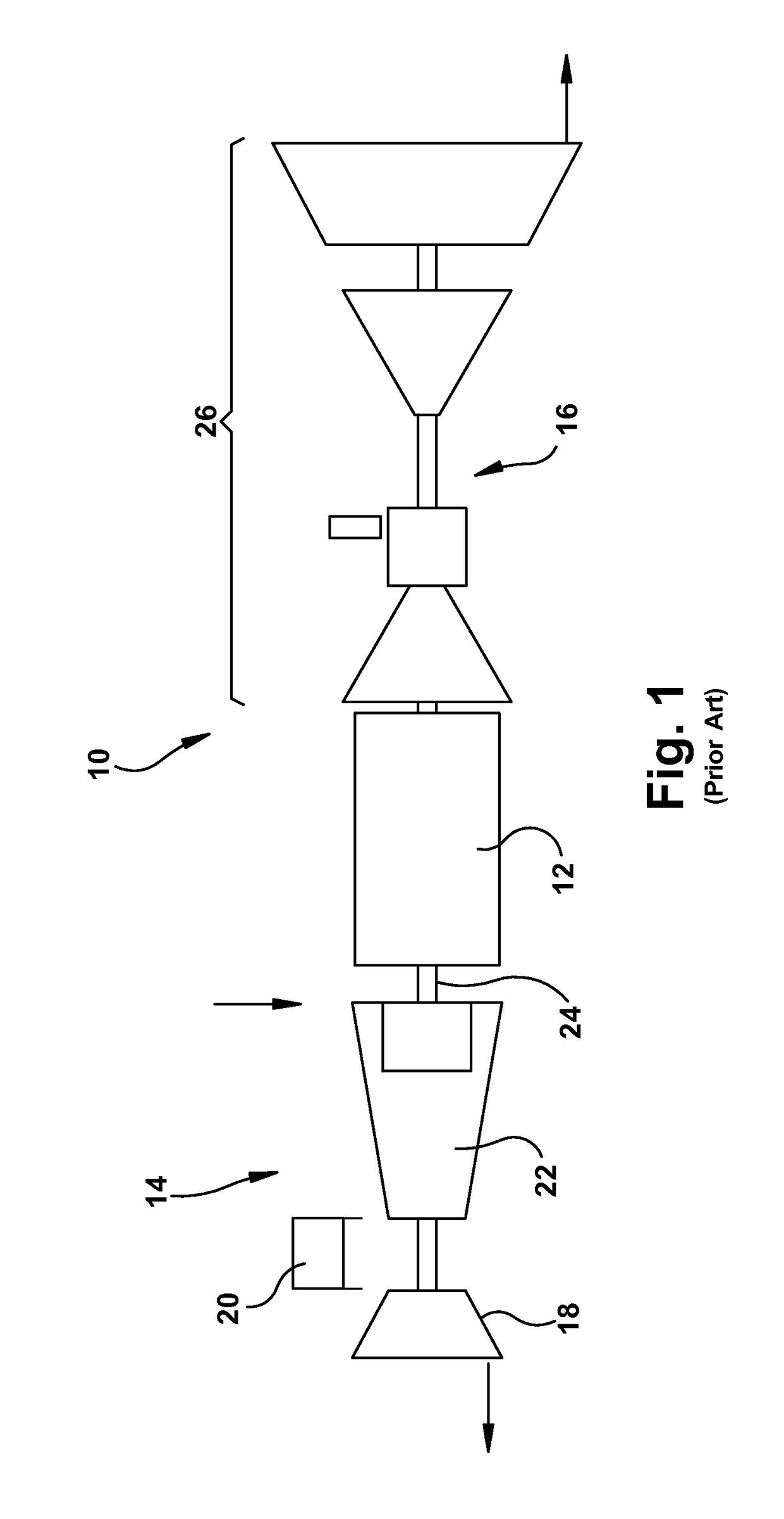
[0053]Referring now to the drawings, particularly to FIG. 1, an industrial machine 10 in one example may include a generator 12. In the example shown, generator 12 is illustrated as part of a single shaft STAG (steam turbine and gas turbine) combined-cycle system, including generator 12 in axial alignment with a gas turbine 14 and a steam turbine system 16. As illustrated, gas turbine 14 includes a compressor 18, a plurality of combustors 20 and a gas turbine section 22 for driving a rotor axially coupled to generator rotor 24. Generator rotor 24 at the opposite end of generator 12 is coupled to a series of high, intermediate and low pressure steam turbines 26 which may utilize the high temperature exhaust from the gas turbine and a heat recovery steam generator (not shown) to convert the gas turbine exhaust into usef...


PUM


Abstract

A method for laterally moving an industrial machine is provided. The method may include: supporting the industrial machine on a pair of rail elements configured to be positioned laterally below and support the industrial machine, the rail elements allowing the industrial machine to be moved laterally from a first operative position to a second, maintenance position. A pair of linear actuators configured to laterally move the industrial machine from the first, operative position to the second, maintenance position.

Description

CROSS-REFERENCE TO RELATED APPLICATIONS[0001]This application claims priority to U.S. Patent Provisional Application No. 62 / 088,153 filed on Dec. 5, 2014. The application identified above is incorporated herein by reference in its entirety for all that it contains in order to provide continuity of disclosure.BACKGROUND OF THE INVENTION[0002]The disclosure relates to a method for moving an industrial machine for maintenance such as a generator from an aligned single shaft gas turbine-generator-steam turbine configuration.[0003]Large industrial machines such as a gas turbine, generator and steam turbine are often aligned with other structures for operation. For example, the gas turbine, generator and steam turbine may be axially aligned in a single shaft configuration one with the other with the generator located between the gas and steam turbines whereby the turbines drive the generator rotor to produce electric power. This configuration is known as a single shaft STAG (steam and gas...

Claims


Application Information

Patent Timeline
Patent Type & Authority Patents(United States)
IPC IPC(8): B66F19/00F16M5/00F16M7/00F01D25/28F16M1/026F16M1/00
CPCF16M1/00F01D25/28F16M1/026Y02T50/672F16M7/00F16M2200/08F16M5/00H02K15/00H02K15/0006H02K15/02Y02T50/60
Inventor DAVI, MICHAEL ALANGEORGE, JAYAN KAADAAPURAMMARTIN, MATTHEW ROBERTO'MEARA, SEAN CORNELIUSYAGIELSKI, JOHN RUSSELL
Owner GE INFRASTRUCTURE TECH INT LLC
Why Eureka
Try Eureka