

Heat conditioning system for a motor vehicle
- Summary
- Abstract
- Description
- Claims
- Application Information
AI Technical Summary
Benefits of technology
Problems solved by technology
Method used
Image

Examples
Embodiment Construction
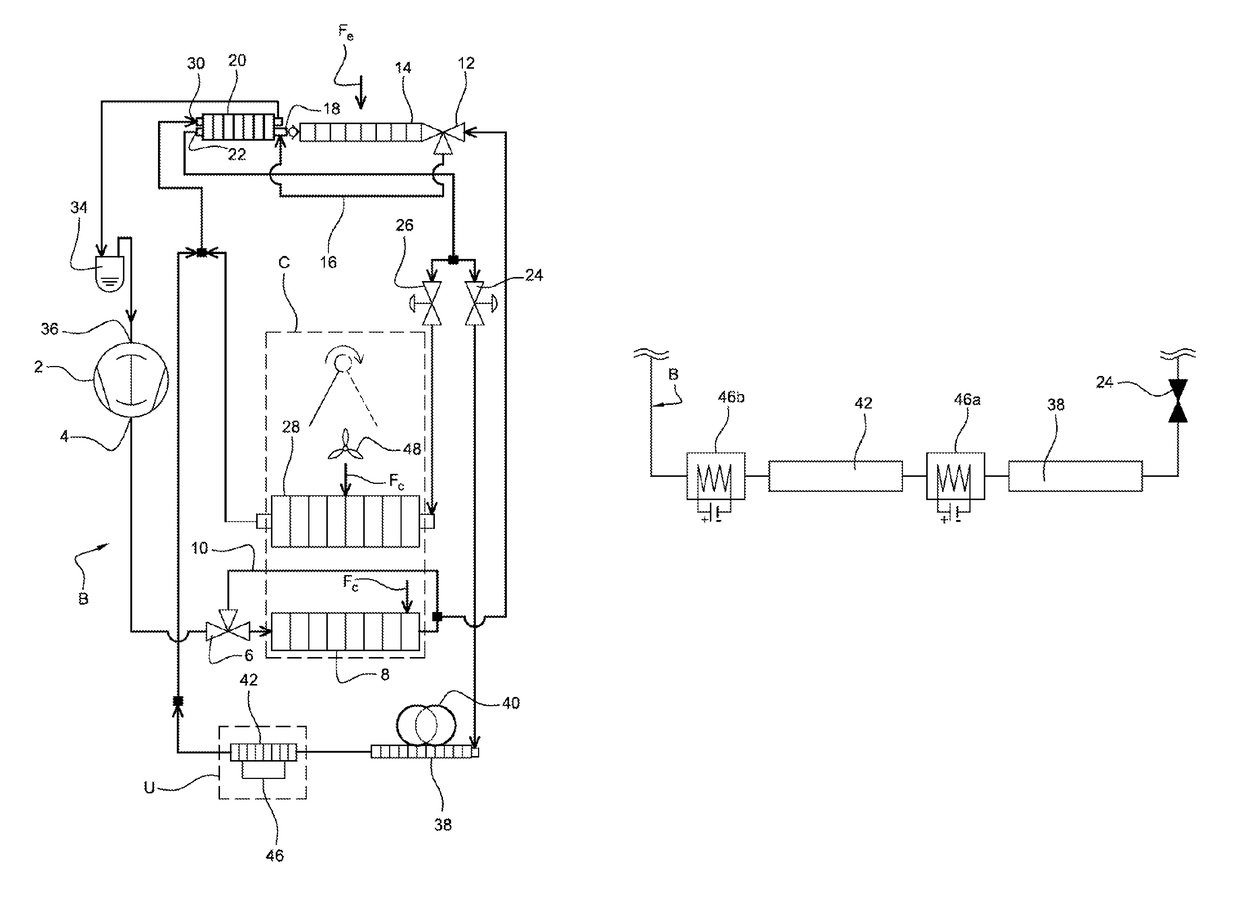
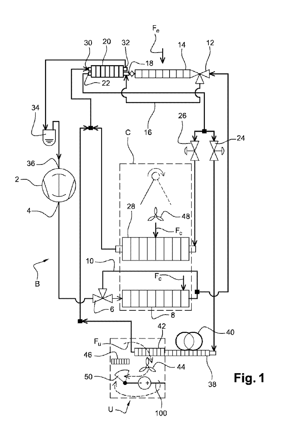
[0046]FIG. 1 represents a schematic view of a heat conditioning system of an electric vehicle according to the invention.
[0047]The heat conditioning system comprises an air conditioning loop B and a heat treatment unit U for a battery 100 of the vehicle.
[0048]This air conditioning loop B comprises a compressor, at least two heat exchangers and at least one decompression device. The compressor is an electric compressor 2 in which a coolant is compressed. The electric compressor 2 comprises an output 4 through which the coolant at high pressure and high temperature is expelled to reach a first three-way valve 6. An input of a heat exchanger, called internal condenser 8, is linked to one of the two outputs of the first three-way valve 6, this internal condenser 8 being located inside an air conditioning installation C. The other output of the first three-way valve 6 leads to a bypass channel 10 ending at an output of the internal condenser 8. Thus, it is possible for the coolant from t...
PUM
 Abstract
Description
Claims
Application Information