Mechanical paintball gun

Inactive Publication Date: 2017-10-31
LAI BAO SHYAN
View PDF6 Cites 5 Cited by
  • Summary
  • Abstract
  • Description
  • Claims
  • Application Information

AI Technical Summary

Benefits of technology

The present invention provides a mechanical paintball gun with a delay mechanism to prevent paintballs from bursting inside the gun while it is being fired continuously. The technical effect is to increase the cycle time for the firing piston to complete a stroke, giving enough time for the paintball to fully enter the percussion zone. The gun has a frame comprising a barrel with two operation chambers and a hammer, which is elastically pushed by a spring and linked with a firing piston to move between a first position and a second position. The first operation chamber has a ball feeding hole and a percussion zone, while the second operation chamber is connected to a high-pressure gas source with a normally closed valve pack that passes high-pressure gas when the hammer is pushed by the spring at the second position status. The frame has a ventilation hole in communication with both operation chambers, and the firing piston has an outlet channel in communication with the ventilation hole when the firing piston is at the second position status. The gun also has a stop member that normally locks the hammer at the first position status and is linked with a trigger that can be swung to separate the stop member from the hammer and unlock the hammer.

Problems solved by technology

However, the conventional mechanical paintball gun can only perform a single shot one time by the aforementioned operation.
In this case, for the successive shooting action, the paintball 5 would be pressed by the firing piston 92 to burst in the barrel 9, which results in failure of the shooting paintball 5 and even breakage of the paintball gun.

Method used


Image

  • Mechanical paintball gun
  • Mechanical paintball gun
  • Mechanical paintball gun

Examples


Embodiment Construction

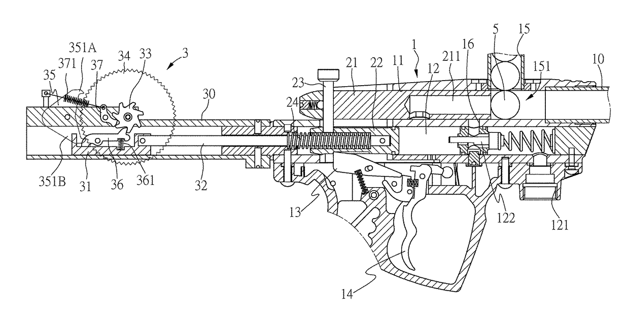
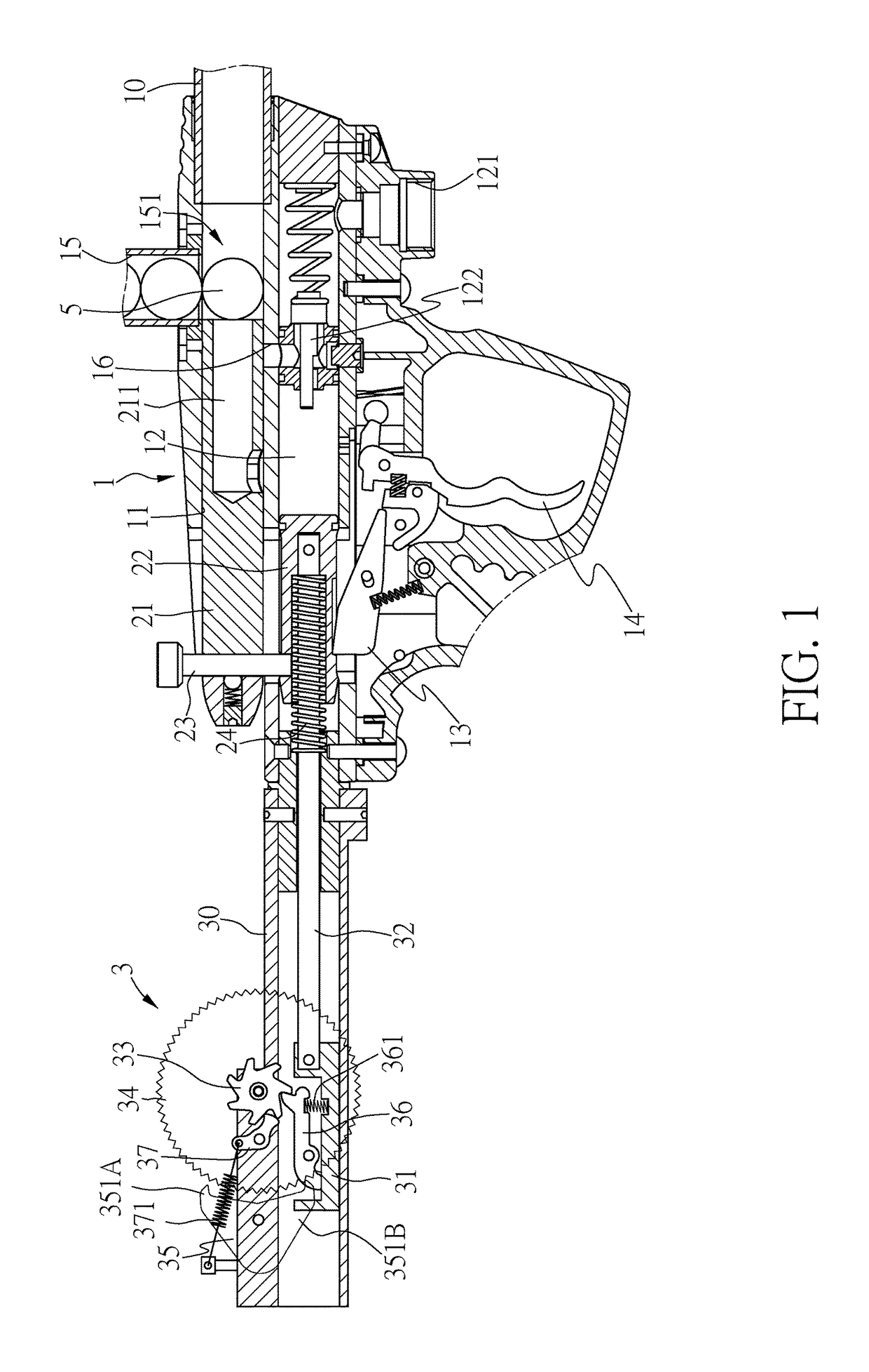
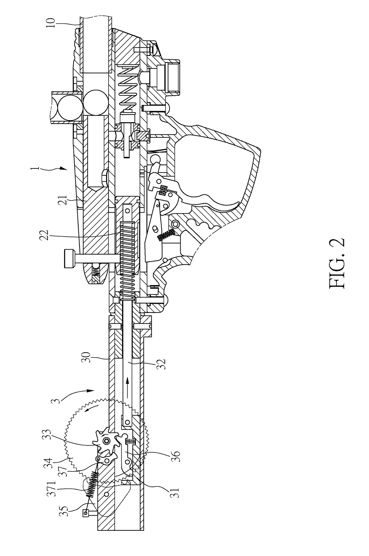
[0034]Please refer to FIG. 1, which shows a mechanical paintball gun according to the first embodiment of the present invention. The mechanical paintball gun comprises a frame 1, which includes a barrel 10. A first operation chamber 11 and a second operation chamber 12 are formed in the frame 1 and parallel to each other. The first operation chamber 11 contains a firing piston 21 that is slidable and corresponding to the barrel 10. The second operation chamber 12 contains a hammer 22. The firing piston 21 and the hammer 22 are linked by a first linking member 23, so that the two can move simultaneously in the first operation chamber 11 and in the second operation chamber 12, respectively. Therein, the hammer 22 is biased by a first spring 24, and when pushed, makes the firing piston 21 and the hammer 22 move from a first position status as shown in FIG. 1 to a second position status as shown in FIG. 3.

[0035]A stop member 13 is pivotally disposed inside the frame 1 to normally lock t...


PUM


Abstract

A mechanical paintball gun has a first operation chamber and a second operation chamber for receiving a firing piston and a hammer, respectively. The firing piston and the hammer move simultaneously between a first position status and a second position status. The second operation chamber is connected with a high-pressure gas source and has a normally closed valve pack. When the hammer moves to the second position status, the valve pack becomes open and allows high-pressure gas to pass therethrough to enter the first operation chamber for shooting paintballs. The second operation chamber contains therein a slidable member and a resistance device. The slidable member is linked with the hammer, and the slidable member pushes the resistance device. With the resistance device slowing down the slidable member to delay a cycle time of a shooting process, paintballs can be fed in time to enable continuous and stable shooting.

Description

CROSS-REFERENCE TO RELATED APPLICATIONS[0001]The present application is a continuation-in-part of U.S. patent application Ser. No. 15 / 281,573, filed on Sep. 30, 2016, titled Mechanical Paintball Gun Capable of Continuously Shooting, listing Bao Shyan Lai as inventor. The above application is incorporated herein by reference in its entirety.BACKGROUND OF THE INVENTION[0002]1. Field of the Invention[0003]The present invention relates to paintball guns, and more particularly to a mechanical paintball gun capable of continuously shooting paintballs.[0004]2. Description of the Related Art[0005]Please refer to FIG. 15 which shows a conventional mechanical paintball gun. In the conventional mechanical paintball gun, a percussion zone 91 is disposed in a barrel 9, and a paintball 5 is ejected out of a bullet cartridge to be fed into the percussion zone 91 for being shot by a firing piston 92. The firing piston 92 is driven to move by a spring 921 and high-pressure gas, and a player can acti...

Claims


Application Information

Patent Timeline
IPC IPC(8): F41B11/642F41B11/723F41B11/73F41B11/70
CPCF41B11/642F41B11/723F41B11/73F41B11/70F41B11/721
Inventor LAI, BAO SHYAN
Owner LAI BAO SHYAN
Why Eureka
Try Eureka