Stocking suction cylinder motion mechanism of integrated machine

A technology of motion mechanism and sock suction cylinder, which is applied in textiles and papermaking, weft knitting, knitting, etc., can solve the problems of reduced service life, increased exercise time, and increased failure rate, so as to shorten the moving distance and time, increase Circular working rhythm, the effect of improving work efficiency

Inactive Publication Date: 2020-05-19
浙江伟焕机械制造股份有限公司
View PDF0 Cites 2 Cited by
  • Summary
  • Abstract
  • Description
  • Claims
  • Application Information

AI Technical Summary

Problems solved by technology

[0002] When the integrated computer hosiery machine is working, the socks knitted in rows are sent out from the output port of the hosiery machine and fall down, and the sock suction tube extended from the lower end is inhaled and then flows out of the special storage bin. When the sock suction tube is not working, it is in a closed state , takes up little space, and the sock-absorbing tube is in the extended state when the sock needs to be sucked. The current kinematic mechanism and stretching motion track state of the sock-suction tube generally have two types. One kind of motion track is as follows: Figure 7 As shown in the figure: the rigid column 1001 of the movement mechanism 1003 is fixed, and the sock suction tube 1002 connected with the rigid column 1001 needs to be translated in the horizontal direction before moving upward when stretching, and it is carried out in two beats. The distance is long, and the movement time of a single beat also increases accordingly. The sock output frequency of the sock machine needs to be synchronized with the movement frequency of the sock tube, which indirectly reduces the overall production efficiency, and the movement is in two relay movements, with intermittent pauses and impacts. The force increases the failure rate and simultaneously reduces the service life; another motion track such as Figure 8 As shown in the figure: the rigid column 1001 of the movement mechanism 1003 is fixed, the lower end of the sock suction tube 1002 is connected with the rigid column 1001 and can be used as a base point to make the sock suction tube 1002 pitch-type movement, and the sock suction tube The upper end of a 1002 is movable and can be stretched or contracted. When working, the upper end of the sock suction tube 1002 is turned outward, and the sock outlet of the sock machine is obliquely sucked in by negative pressure, because the sock output is vertical. Downward, the socks that come out are also vertically downward due to the action of gravity. The oblique sock suction tube 1002 needs to change the moving direction of the vertically downward socks into the sock suction tube 1002. In practice, a large proportion of socks are sucked. Socks failed and fell off and need to be stored manually

Method used


Image

  • Stocking suction cylinder motion mechanism of integrated machine
  • Stocking suction cylinder motion mechanism of integrated machine
  • Stocking suction cylinder motion mechanism of integrated machine

Examples


Embodiment Construction

[0026] The technical solutions of the present invention will be further specifically described below through the embodiments and in conjunction with the accompanying drawings.

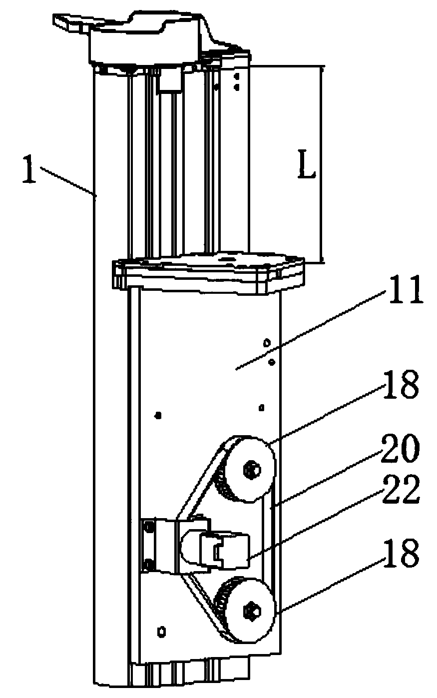
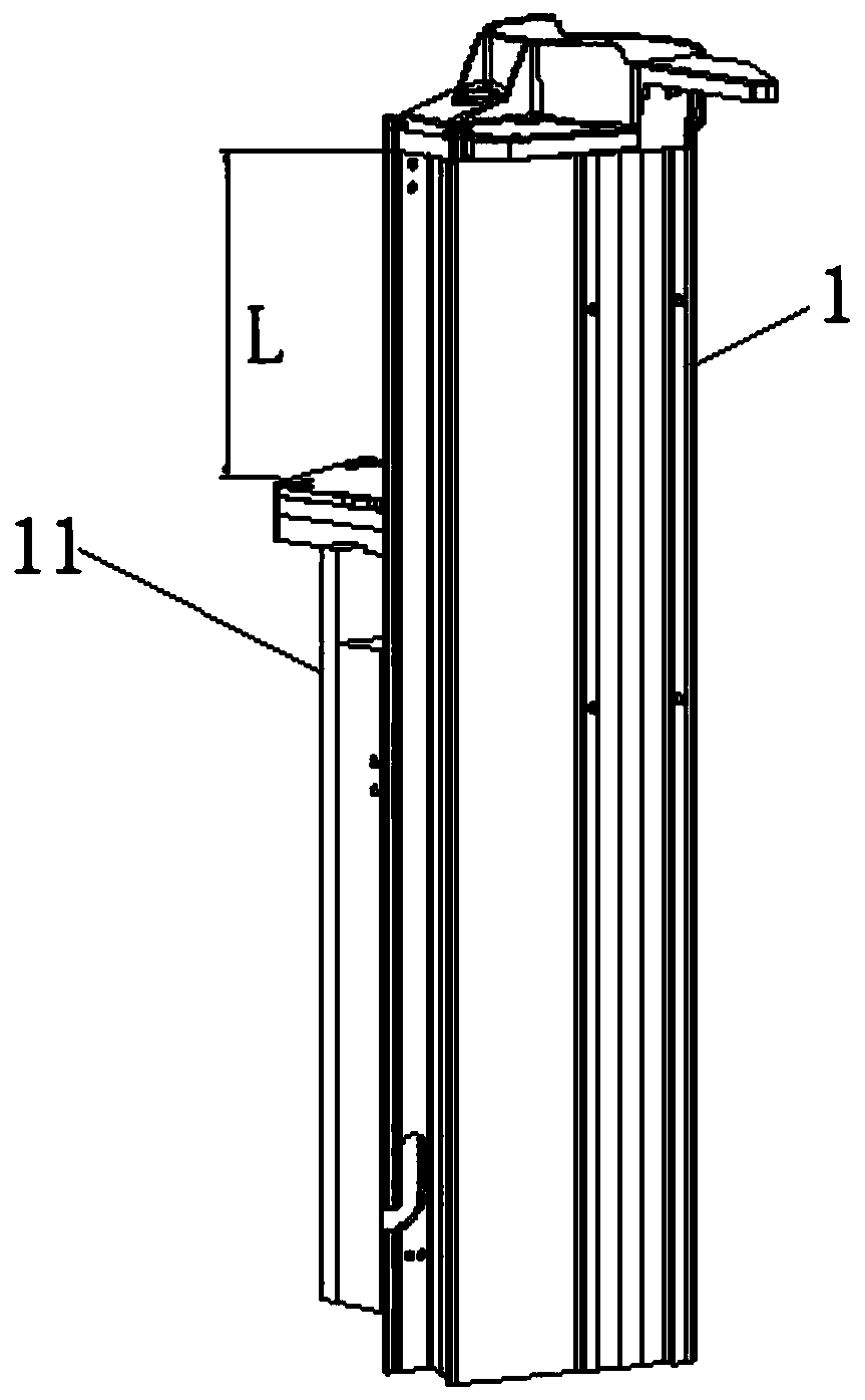
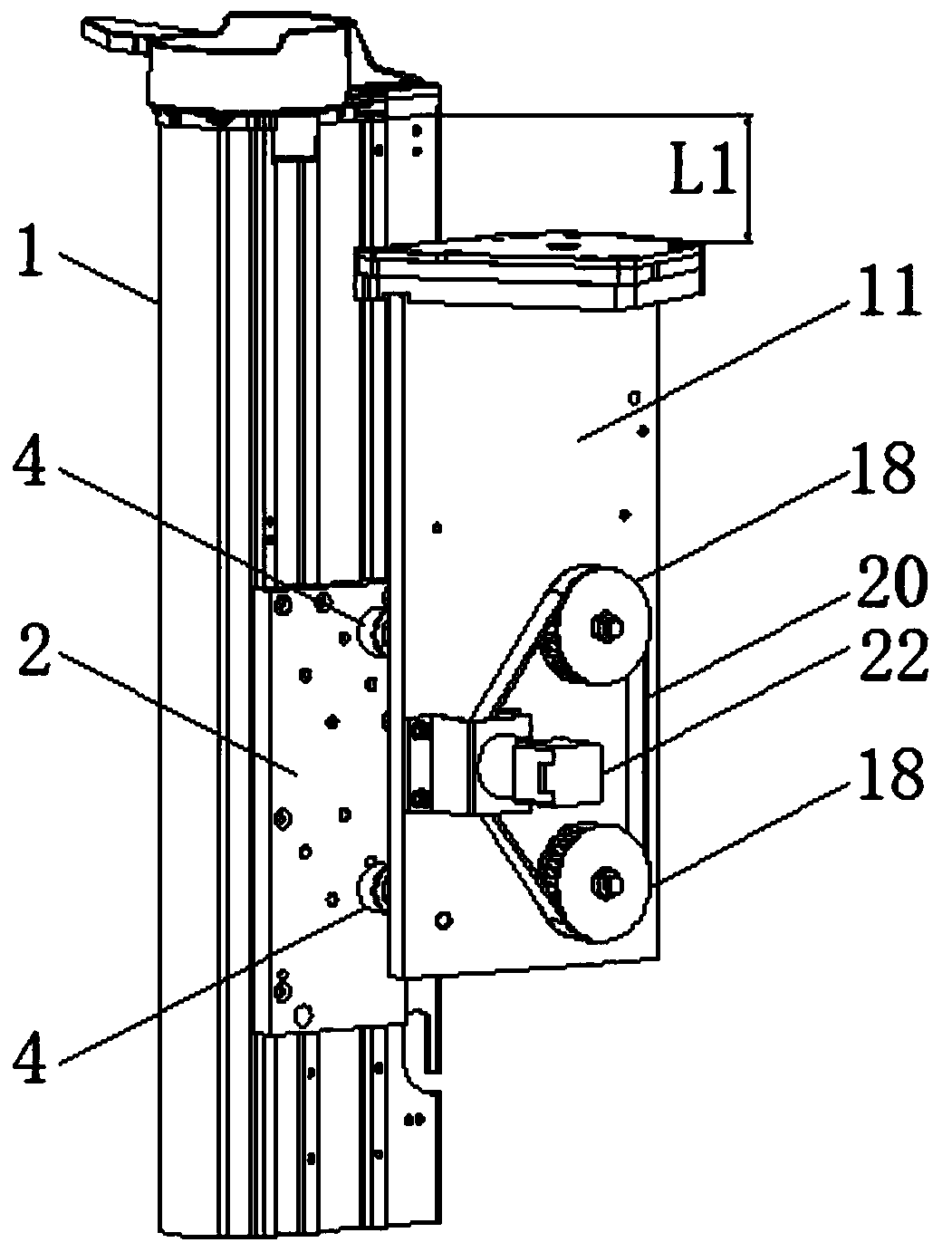
[0027] like figure 1 , figure 2 , Figure 5 As shown in the figure, the kinematic mechanism of the all-in-one sock suction tube, the fixed plate 2 is installed on the side of the rigid column 1, the fixed plate 2 is fixedly installed with the body of the hosiery machine, and two axial screws 3 are installed on the fixed plate 2,

[0028] Both ends of the rocker arm 4 are provided with through holes, and deep groove ball bearings-5 are arranged in the through holes at one end of the rocker arm 4. The deep groove ball bearings-5 are connected with the short shaft at the other end of the shaft position screw 3 and fixed axially. To avoid disengagement, the rocker arm 4 connected with the shaft screw 3 can be tilted and flipped;

[0029] The two ends of the limit block 10 are fixedly installed on one ...


PUM


Abstract

The present invention discloses a stocking suction cylinder motion mechanism of an integrated machine. A fixed plate is installed on the side surface of a rigid column; one ends of two axial screws are connected with the fixed plate, and the other ends of the two axial screws are connected with bearings in through holes in one ends of rocker arms; the connected rocker arms can be turned over in apitching manner; the upper end of a guide rail mounting plate provided with a limiting block on the side surface is provided with a stocking suction cylinder mounting plate; two bearing holes of the guide rail mounting plate are internally provided with bearings and the bearings are connected with studs; one ends of the two studs and the through holes in the other ends of the corresponding rockerarms are fixed, and the other ends of the two studs are connected with synchronous belt wheels; a drive motor with a rotating shaft provided with a synchronous belt wheel II is connected with a motorseat; the motor seat and the guide rail mounting plate are fixed; and a synchronous belt forms transmission connection around the synchronous belt wheel II and the two synchronous belt wheels. A linear motion track path is short, thereby greatly shortening the moving distance and time of a stocking suction cylinder, improving the cycle work beat of the stocking suction cylinder, and improving theworking efficiency; and an inlet of the stocking suction cylinder is upwards all the time, so that output stockings can enter the inlet of the stocking suction cylinder smoothly without interference.

Description

technical field [0001] The invention relates to the technical field of hosiery machines, in particular to a kinematic mechanism for an all-in-one hosiery suction tube. Background technique [0002] When the integrated computer hosiery machine is working, the socks knitted in rows are sent out from the output port of the hosiery machine and fall down, and the sock suction tube extended from the lower end is inhaled and then flows out of the special storage bin. When the sock suction tube is not working, it is in a closed state , takes up little space, and the sock-absorbing tube is in the extended state when the sock needs to be sucked. The current kinematic mechanism and stretching motion track state of the sock-suction tube generally have two types. One kind of motion track is as follows: Figure 7 As shown in the figure: the rigid column 1001 of the movement mechanism 1003 is fixed, and the sock suction tube 1002 connected with the rigid column 1001 needs to be translated i...

Claims


Application Information

Patent Timeline
Patent Type & Authority Applications(China)
IPC IPC(8): D04B15/88
CPCD04B15/88
Inventor 俞伟欢蒋志球
Owner 浙江伟焕机械制造股份有限公司
Why Eureka
Try Eureka