Component mounting apparatus

a technology for mounting apparatuses and components, applied in the direction of angle measurement, manufacturing tools, instruments, etc., can solve the problems of reducing the productivity of the electronic component mounting apparatus, the inability to perform hold posture inspection, and the combination of components in which the hold posture inspection itself is impossible, so as to improve the productivity of the component mounting apparatus, improve the accuracy of hold posture inspection, and the diameter of lenses can be larger.

Inactive Publication Date: 2007-04-05
PANASONIC CORP
View PDF7 Cites 26 Cited by
  • Summary
  • Abstract
  • Description
  • Claims
  • Application Information

AI Technical Summary

Benefits of technology

[0044] With the configuration of the ninth aspect, even in the case, by providing the reflecting/transmitting member between the entrance port and the sensors and arranging the sensors of the inspection unit alternately on the reflected light side and the transmitted light side in the reflecting/transmitting member, and arranging lenses between the reflecting/transmitting member and the respective sensors, the diameter of lenses can be larger. Therefore, it is possible to improve the accuracy of the hold posture inspection of the components sucked by the nozzles provided on the head, and as a result, to improve the productivity of the component mounting apparatus.
[0045] According to a tenth aspect of the present invention, a reflecting/transmitting member including a half mirror or a prism may be provided between the entrance port and the sensors, and another sensor may be additionally disposed at any position corresponding to a transmitted light side of the reflecting/transmitting member where an image is capable to be taken. With such a configuration, it is possible to improve the accuracy of the hold posture inspection by taking in image information of a component with a sensor optimum for the hold posture inspection of the component sucked by each nozzle among a plurality of sensors of the inspection unit. Further, since the number of the sensors is increased, the accuracy of the posture inspection of the components sucked by the nozzles can be improved, and also the inspection object components are expanded. As a result, it is possible to improve the prod...

Problems solved by technology

However, the conventional electronic component mounting apparatus had a following problems.
Therefore, there may be a case of a combination of components in which the inspection accuracy in the hold posture inspection is not secured through one scanning operation, or a combination of components in which the hold posture inspection itself is impossible.
As a result, there is a case where the productivity in the electronic component mounting apparatus is reduced.
Further, since pieces of hold posture information of components sucked by...

Method used


Image

  • Component mounting apparatus
  • Component mounting apparatus
  • Component mounting apparatus

Examples


first embodiment

(First Embodiment)

[0098] Hereinafter, a first embodiment of the present invention will be explained using FIGS. 1 to 6.

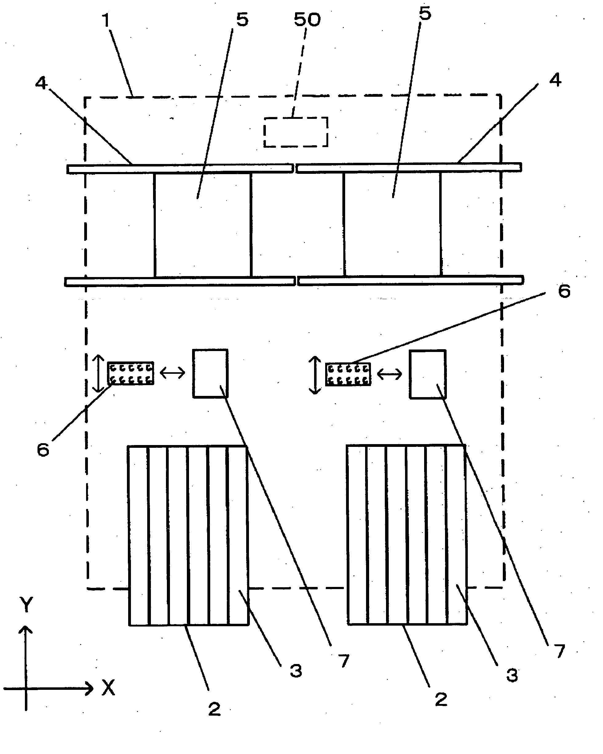
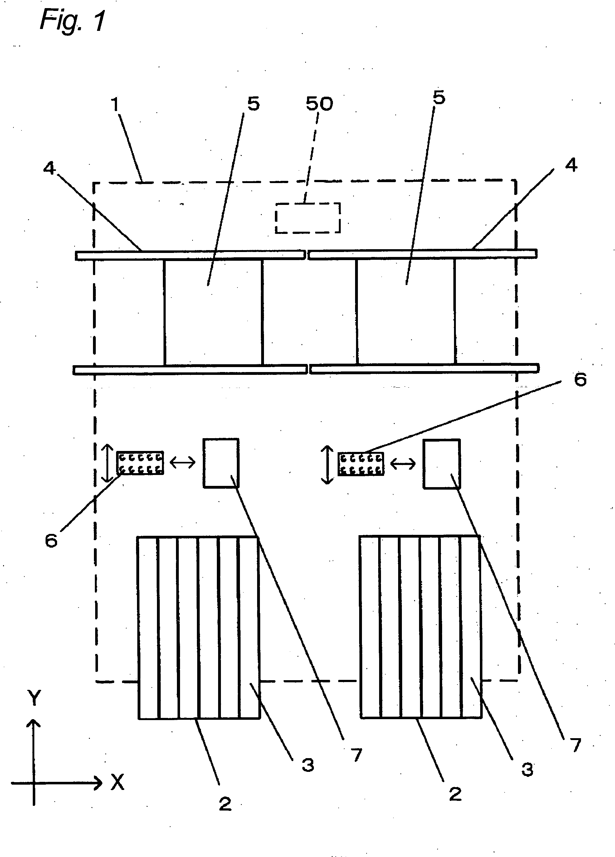
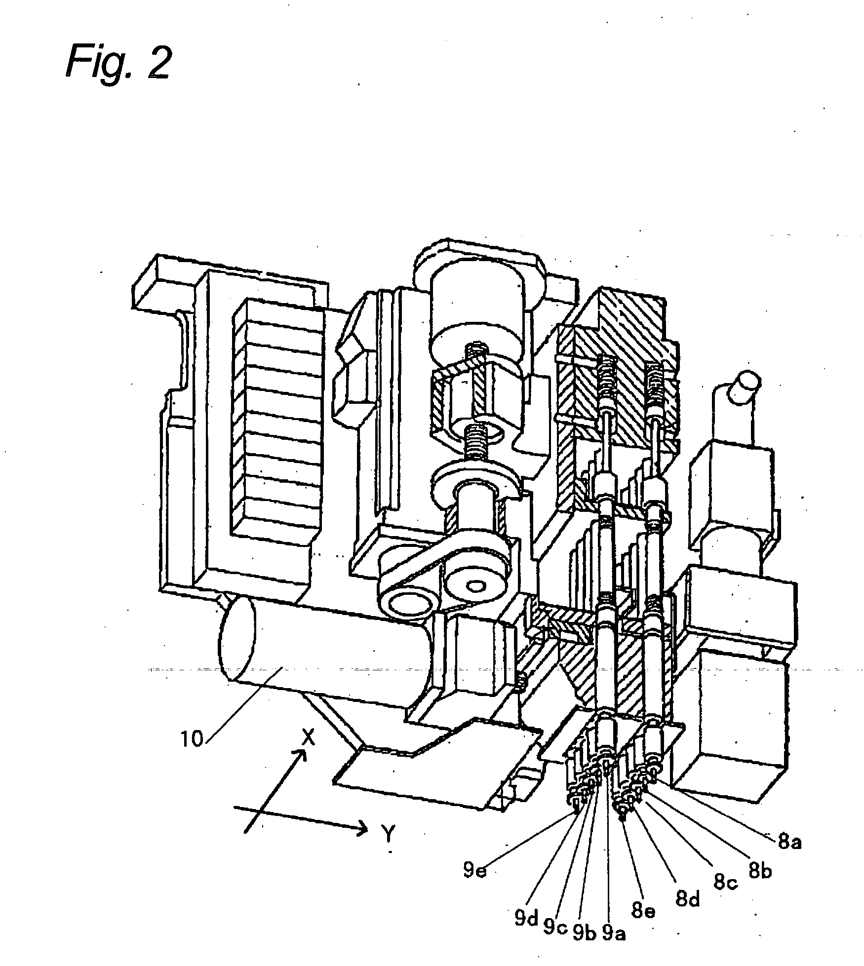
[0099]FIG. 1 is a schematic plan view showing a component mounting apparatus of the first embodiment in the present invention; FIG. 2 is a perspective view showing a head of the electronic component mounting apparatus; and FIGS. 3 to 6 are: a plan view showing an inspection unit of the electronic component mounting apparatus, a timing chart of taking image information (hereinafter referred to as “image pickup” or “imaging”) of components sucked by nozzles in the inspection unit, a sectional view of the inspection unit, and a side view of the inspection unit.

[0100] As shown in FIG. 1, a supplying unit 2 has a plurality of supplying parts for supplying components (not shown in FIG. 1), and components supplied by the supplying unit 2 are sucked and held by a plurality of nozzles (described later) provided on a head 6 movable in X and Y directions, and are mounted on ...

second embodiment

(Second embodiment)

[0113] Next, a second embodiment of the present invention will be explained by using FIGS. 7 and 8.

[0114] The second embodiment of the present invention has a similar configuration to that of the first embodiment, except that a reflecting / transmitting member 20 is arranged between the first and second entrance ports 17 and 18 and the first and second sensors 13 and 14 instead of the reflector 19, and additional sensors are arranged on a transmitted light side of the reflecting / transmitting member 20. Therefore, the similar constitutional parts are denoted by the same reference numerals, and detailed explanations thereof are omitted.

[0115] In FIGS. 7 and 8, the reference numeral 20 indicates the reflecting / transmitting member such as a half mirror or a prism, and the reference numerals 13 and 21 are the first sensor and a first spare sensor provided on a reflected light side of the reflecting / transmitting member 20 and on the transmitted light side of the reflect...

third embodiment

(Third Embodiment)

[0118] Next, a third embodiment of the present invention will be explained using FIGS. 9 to 11.

[0119] The third embodiment of the present invention has a similar configuration to that of the first embodiment, except that a reflecting / transmitting member 20 is arranged between the entrance ports and the sensors instead of the reflector 19 and the second sensor 14 for performing pickup image for the hold posture inspection of the second components 12a and 12b sucked by the nozzles 9a and 9b of the second nozzle row arranged on the side faces of the inspection unit 7 is arranged on the transmitted light side of the reflecting / transmitting member 20, and that lenses for the first and second sensors 13 and 14 are arranged between the reflecting / transmitting member 20 and the first and the second sensors 13 and 14. Therefore, the similar constitutional parts are denoted by the same reference numerals, and detailed explanations thereof are omitted.

[0120] In FIGS. 9 to 1...


PUM

PropertyMeasurementUnit
Angleaaaaaaaaaa
Heightaaaaaaaaaa
Displacementaaaaaaaaaa

Abstract

The present invention is intended to realize a hold posture inspection of a plurality of components sucked by a plurality of nozzle rows provided on a head with a single scanning operation, thereby reducing the time for the hold posture inspection and improving the accuracy thereof. In order to achieve such objections, the present invention includes: a head on which at least two nozzle rows are disposed, each of which includes at least one nozzle; a circuit board holding unit for holding a circuit board on which components conveyed by the head are mounted; and an inspection unit, provided on a moving path of the head from a supplying unit to the circuit board holding unit, for inspecting hold postures of the components held by the nozzles of the head and including sensors for posture inspection independent for the respective nozzle rows.

Description

BACKGROUND OF THE INVENTION [0001] 1. Field of the Invention [0002] The present invention relates to a component mounting apparatus for mounting components such as electronic components on a board such as a circuit board. [0003] 2. Description of the Related Art [0004] Conventionally, an electronic component mounting apparatus has been so configured that components supplied from a supplying unit are taken out by being sucked with nozzles of a head, and conveyed onto a circuit board held by a circuit board holding unit, and then, mounted on the circuit board. The hold postures of the components sucked and held by the nozzles are inspected by an inspection unit provided on a moving path of the head, and based on the inspection results, the hold postures of the components are corrected as required and then a mounting operation is performed. [0005] The head is provided with a plurality of nozzles. When the hold postures of the components sucked by the nozzles are inspected by the inspec...

Claims


Application Information

Patent Timeline
IPC IPC(8): H05K3/30B23P21/00H05K13/04
CPCH05K13/0413Y10T29/4913Y10T29/53174Y10T29/53187Y10T29/53087Y10T29/49131Y10T29/53178Y10T29/53052Y10T29/49004H05K13/041H05K13/0812
Inventor OTA, HIROSHINAKAI, NOBUHIROKAWASUMI, KENSUKEIIZUKA, KIMIOUEMORI, HIROTSUGUMOCHIDA, YOSHINORIIZUMIDA, KEIZO
Owner PANASONIC CORP
Why Eureka
Try Eureka