
Method for braking a traction vehicle-trailer combination with reduced trailer braking force as a function of the response of the ABS of the traction vehicle

a technology of traction vehicle and traction vehicle, which is applied in the direction of automatic initiation, braking system, etc., can solve the problems of trailer swinging out with respect, trailer loss of lateral guidance, and poor traction control accuracy

Active Publication Date: 2017-11-07
KNORR-BREMSE SYST FUER NUTZFAHRZEUGE GMBH
View PDF16 Cites 9 Cited by
  • Summary
  • Abstract
  • Description
  • Claims
  • Application Information

AI Technical Summary

Benefits of technology

[0011]In view of the above, an object of the invention is based on the object of providing a method and a brake device of the type mentioned at the beginning in such a way that undesired swinging out of the trailer can be avoided with as little expenditure as possible.
[0024]Alternatively or additionally, the reduction of the braking force of the trailer or of the braking of the trailer can be carried out by reducing a permissible slip limit of the brake pressure controller of the traction vehicle. Therefore, if, for example, the permissible slip limit of the traction controller is lowered by, usually, between 12% and 14% to 7%, a low braking force or braking is generated for the traction vehicle and trailer compared to the braking force or braking which is generated in the case of a customary relatively high slip limit.
[0025]According to one development, the reduction of the braking force of the trailer is carried out in comparison to the reference braking force as a function of the load of the trailer, a ratio between the load of the trailer and the load of the traction vehicle and / or as a function of a ratio of the contact forces of the wheels of the traction vehicle to those of the trailer. For example, the lower the load of the trailer, the greater the reduction in the braking force of the trailer, in order to avoid locking of the trailer brakes and an associated lack of lateral guidance. Conversely, the higher the load of the trailer, the smaller the reduction in the trailer braking force which is set. The dependence of the reduction of the trailer braking force with respect to the reference braking force on the specified factors can be stored, for example, in a characteristic diagram. The control and evaluation device then interacts with sensors which directly or indirectly determine the load of the traction vehicle and / or the load of the trailer. Consequently, the load can also be estimated using the differential slip at various axles, with the result that in this case the sensors are wheel speed sensors and do not have to be load sensors.

Problems solved by technology

In the case of brake devices of traction vehicle-trailer combinations in which the brake system for the traction vehicle is equipped with a traction controller, but the brake system of the trailer is not, the problem arises that in the case of a braking process, in particular in bends, the trailer can experience a loss of lateral guidance, which, in turn, causes the trailer to swing out with respect to the traction vehicle.
However, this problem also occurs in trailers whose brake system has a traction controller for the axles which are present, but in which brake system the brake slip is determined by wheel speed sensors on fewer axles than the number of axles which are present, for example on only the wheels of one axle.
Such a traction controller is rather imprecise, in particular if, for example, the single axle of the trailer at which the determination of the wheel brake slip is carried out has the highest load, and consequently the other axles which are loaded to a lesser degree then experience blocking by the traction control process which is carried out at the one axle after wheel slip has been detected.
In this case, insufficient lateral guiding force to avoid swinging out of the trailer may also be generated at the wheels of the axles of the trailer.
However, such procedure requires additional hardware and is therefore relatively costly.

Method used


Image

  • Method for braking a traction vehicle-trailer combination with reduced trailer braking force as a function of the response of the ABS of the traction vehicle
  • Method for braking a traction vehicle-trailer combination with reduced trailer braking force as a function of the response of the ABS of the traction vehicle
  • Method for braking a traction vehicle-trailer combination with reduced trailer braking force as a function of the response of the ABS of the traction vehicle

Examples


Embodiment Construction

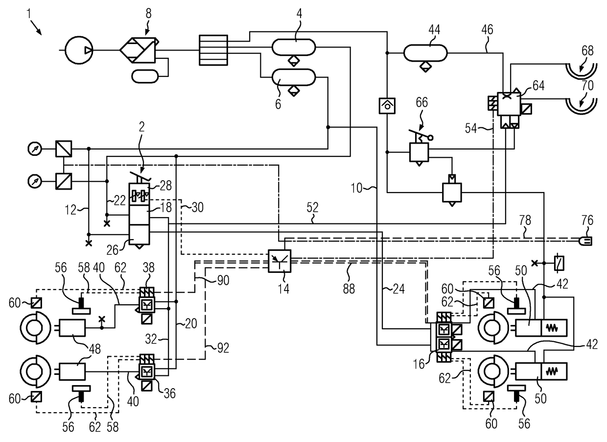
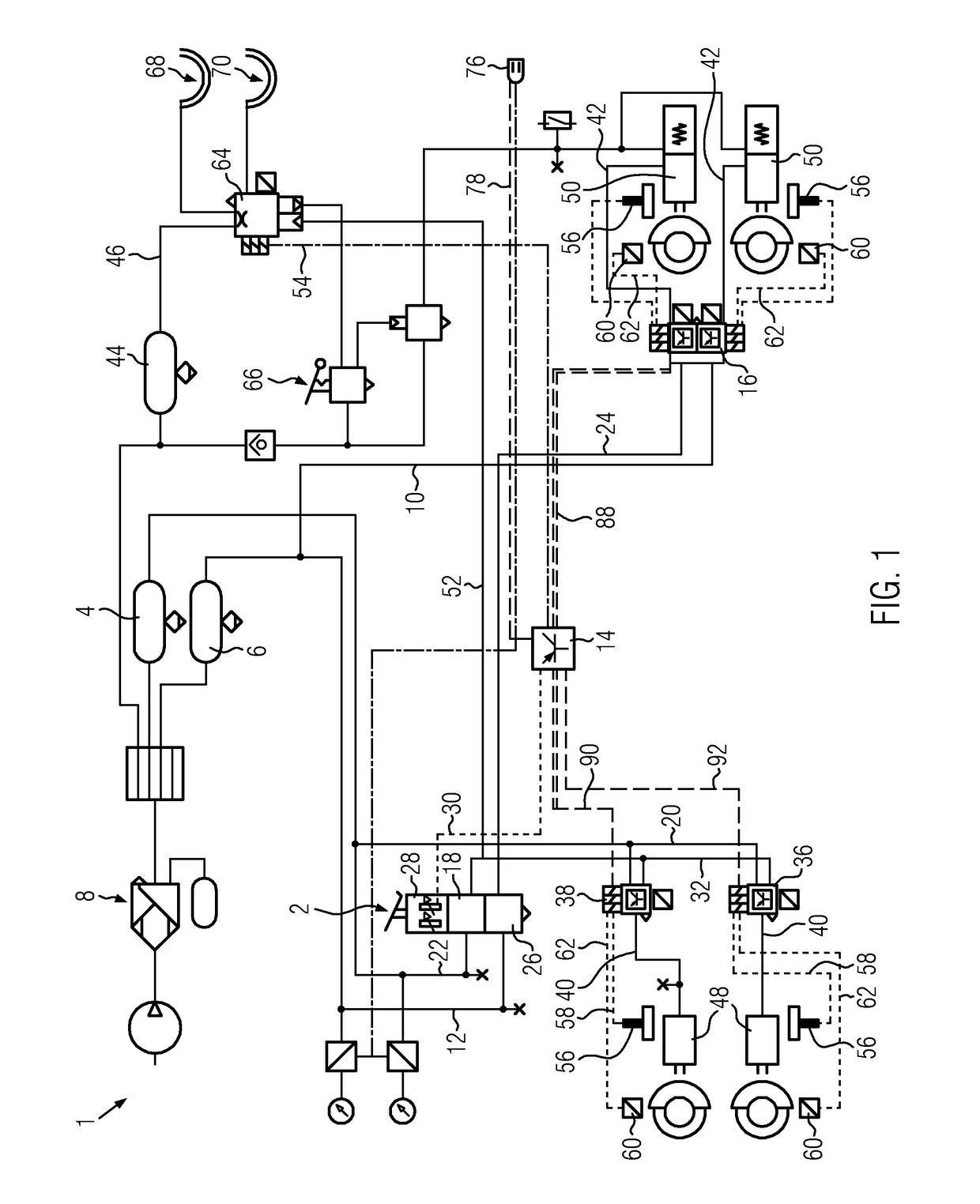
[0035]FIG. 1 is a schematic view of an exemplary embodiment of a service brake system 1 of a traction vehicle of a traction vehicle-trailer combination. In the present case, the traction vehicle-trailer combination has merely a 2-axle semitrailer, but a drawbar trailer or a plurality of drawbar trailers can also be attached to the traction vehicle.

[0036]In this context, the service brake system 1 of the traction vehicle is formed, for example, by an electropneumatic friction brake system in the form of an electronically controlled brake system (EBS; electronic brake system).

[0037]In the case of such an electronically controlled brake system (EBS), pressure control modules 16, 36, 38 are present on axles or wheels, with integrated inlet valves, outlet valves and back-up valves as well as with pressure sensors for sensing the actual brake pressure and with superordinate control electronics for coordinating the actual brake pressures with the setpoint brake pressures according to the r...


PUM


Abstract

A method and device for braking a traction vehicle-trailer combination with a traction vehicle and at least one trailer, in which a traction controller is provided for a brake system of the traction vehicle, and for a brake system of the at least one trailer, no traction controller is provided or a traction controller is provided for the axles which are present, but with a brake-slip-determining arrangement on fewer axles than the number of axles, in which (a) the trailer brake system is controlled by the traction vehicle brake system, and (b) during a braking it is determined whether there is a risk of the trailer swinging out as to the traction vehicle, or whether such swinging is imminent or is occurring, and (c) the braking force or the braking of the trailer is reduced if it has been determined in (a) that there is a risk of the trailer swinging out, or is imminent or is occurring, and (d) a risk of the trailer swinging out, or imminent or occurring swinging out of the trailer, as to the traction vehicle, is detected according to (a) by the traction controller.

Description

FIELD OF THE INVENTION[0001]The present invention relates to a method for braking a traction vehicle-trailer combination with reduced trailer braking force as a function of the response of the ABS of the traction vehicle.[0002]The present invention relates to a method for braking a traction vehicle-trailer combination, in which method a traction controller is provided for a brake system of the traction vehicle, and for a brake system of the trailer, no traction controller is provided or a traction controller is provided for the axles which are present, but with a brake-slip-determining arrangement on fewer axles than the number of axles which are present, wherein the brake system of the trailer is controlled by the brake system of the traction vehicle, and during a braking process it is determined whether there is a risk of the trailer swinging out with respect to the traction vehicle, or whether such swinging out is imminent or is occurring, and the braking force of the trailer or ...

Claims


Application Information

Patent Timeline
Patent Type & Authority Patents(United States)
IPC IPC(8): B60T8/17B60T7/20
CPCB60T8/1708B60T7/20B60T2230/06
Inventor HUMMEL, STEFENJUNDT, OLIVER
Owner KNORR-BREMSE SYST FUER NUTZFAHRZEUGE GMBH
Learn More