
Pneumatic fender and mouth piece metal for pneumatic fender

a pneumatic fender and pneumatic fender technology, which is applied in the direction of functional valve types, valve construction, transportation and packaging, etc., can solve the problems of inability to detach the safety valve, the fender bladder is not working properly, and the air is violently ejected from the cavity, so as to reduce the internal pressure of the cavity, prevent damage, and reduce labor and time. the effect of these operations

Active Publication Date: 2017-11-07
THE YOKOHAMA RUBBER CO LTD
View PDF12 Cites 1 Cited by
  • Summary
  • Abstract
  • Description
  • Claims
  • Application Information

AI Technical Summary

Benefits of technology

[0004]The present technology provides a pneumatic fender and a mouth piece metal for a pneumatic fender with significantly enhanced maintainability wherein a safety valve can be attached and detached and a confirmation test of the valve opening pressure of the safety valve can be performed on the pneumatic fender while in use, and the labor and time required for these operations are greatly reduced.
[0021]a safety valve that, upon an internal pressure of a cavity of a fender bladder reaching a pressure threshold, opens to connect the cavity of the fender bladder to outside air and reduce the internal pressure;
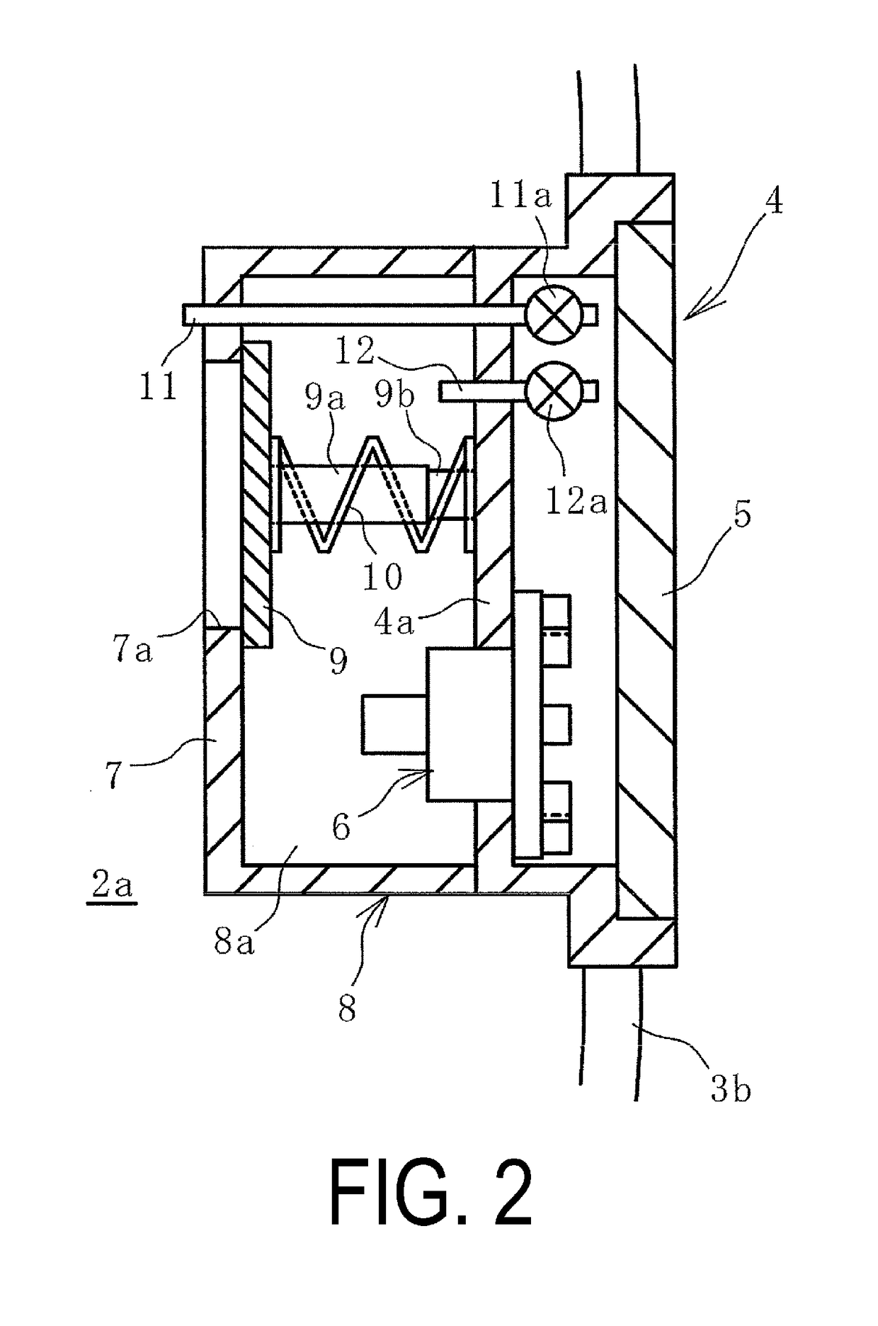
[0032]According to the present technology, the mouth piece metal includes a receiving chamber that isolates the safety valve from the cavity of the fender bladder, a through hole that connects a cavity of the receiving chamber and the cavity of the fender bladder, the through hole being formed on a dividing wall constituting the receiving chamber, an open / close valve that opens and closes the through hole, and a resilient member that constantly biases the open / close valve toward a closing direction of the through hole, wherein upon the internal pressure of the cavity of the fender bladder being less than the pressure threshold and greater than a standard pressure, which is a sum of a predetermined initial internal pressure and an allowable pressure, the open / close valve opens, opening the closed through hole. Thus, when the internal pressure of the cavity of the fender bladder reaches or exceeds the pressure threshold, the open / close valve opens, and the cavity of the fender bladder and the cavity of the receiving chamber are connected via the through hole and the safety valve opens. Accordingly, the safety valve functions as per convention and prevents damage by reducing the internal pressure of the cavity of the fender bladder when excessively compressed.
[0033]When the internal pressure of the cavity of the fender bladder is equal to or less than the standard pressure, which is the sum of the predetermined initial internal pressure and the allowable pressure, the open / close valve closes and the through hole is closed. Accordingly, in the typical in-use state of the fender bladder, the through hole is closed and the safety valve is isolated from the cavity of the fender bladder by the receiving chamber. Accordingly, the safety valve can be safely detached from the mouth piece metal and safely attached to the mouth piece metal. Thus, the safety valve can be detached and attached from an in-use pneumatic fender while in use without bringing the pneumatic fender onto land or a marine vessel.
[0034]The mouth piece metal further includes the receiving chamber communication passage that connects the cavity of the receiving chamber and outside air and the receiving chamber open / close valve that opens and closes the receiving chamber communication passage. This configuration allows the safety valve to be isolated from the cavity of the fender bladder, thus allowing the receiving chamber open / close valve to be opened and the internal pressure of the cavity of the receiving chamber to be raised to the pressure threshold via the receiving chamber communication passage. In other words, a confirmation test of the valve opening pressure of the safety valve can be performed on the pneumatic fender while in use. In such a manner, according to the present technology, the safety valve can be detached and attached and a confirmation test of the valve opening pressure can be performed on the pneumatic fender while in use. As such, the labor and time required for these operations can be greatly reduced, and maintainability can be significantly enhanced.

Problems solved by technology

If the fender bladder remains sealed when the fender is excessively compressed, the internal pressure in the cavity may increase beyond a preset pressure threshold and cause failure of the fender bladder.
However, the cavity of the fender bladder of such a pneumatic fender when in use is inflated to a predetermined internal pressure, and so detaching the safety valve from the mouth piece metal of the fender bladder when the pneumatic fender is in use would result in air being violently ejected from the cavity.
Thus, such detachment of the safety valve is not possible.
Accordingly, the maintenance of detaching and attaching the safety valve to the mouth piece metal requires a great deal of man-hours and time.

Method used


Image

  • Pneumatic fender and mouth piece metal for pneumatic fender
  • Pneumatic fender and mouth piece metal for pneumatic fender
  • Pneumatic fender and mouth piece metal for pneumatic fender

Examples


Embodiment Construction

[0040]Hereinafter, a pneumatic fender and a mouth piece metal for a pneumatic fender of the present technology will be described with reference to embodiments illustrated in the drawings.

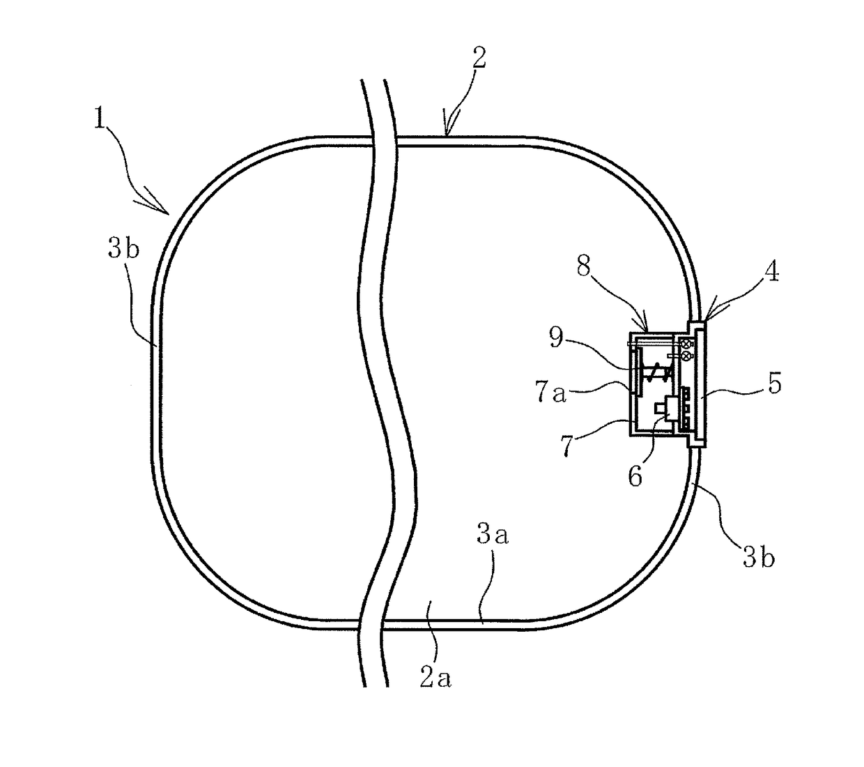
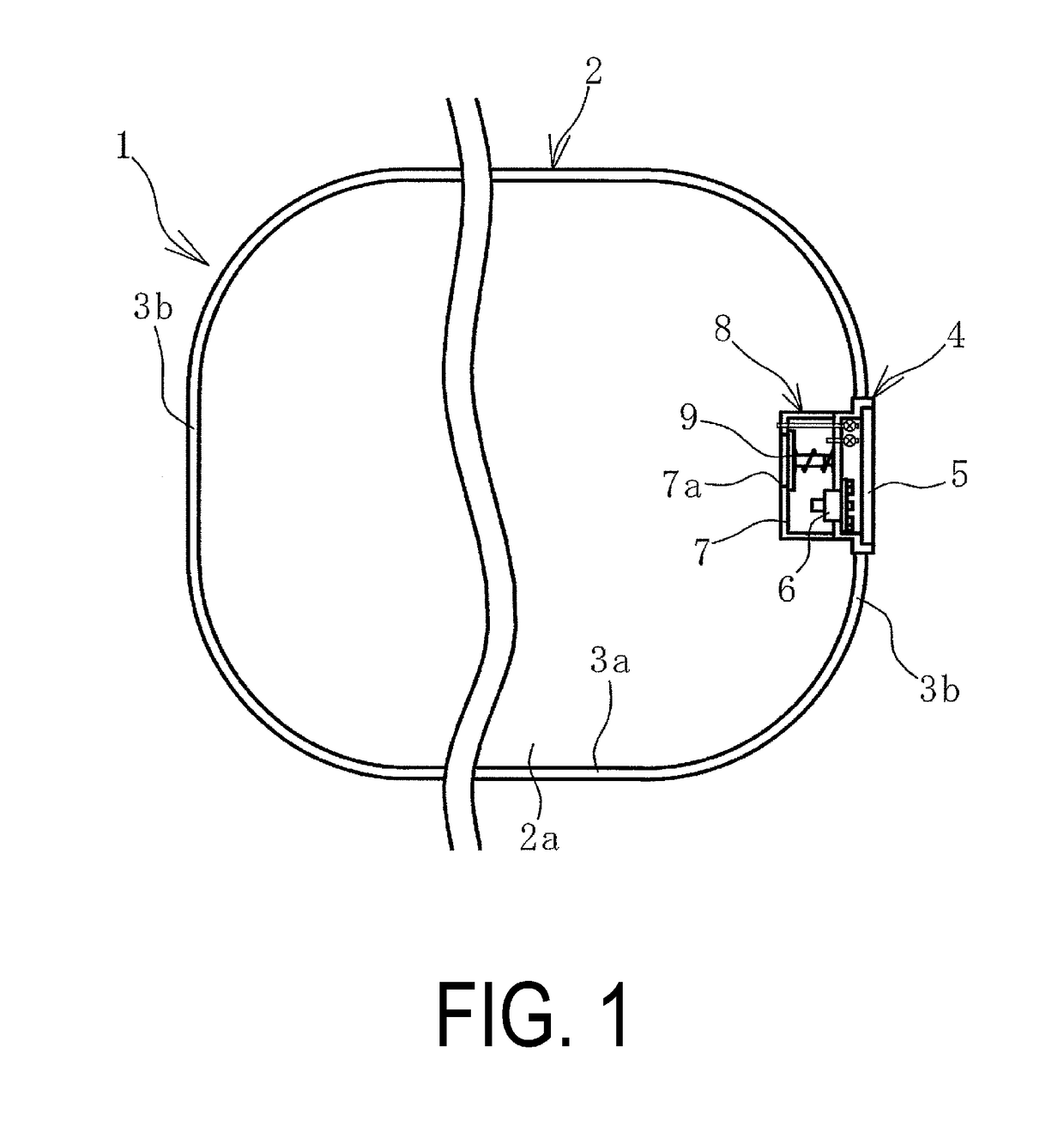
[0041]A pneumatic fender 1 (hereinafter, also fender 1) of the present technology illustrated in FIG. 1 to FIG. 3 includes a fender bladder 2 that is made mainly of rubber and has reinforcing material embedded therein. The fender bladder 2 is formed with a cylindrical portion 3a and a bowl-like hemispherical portion 3b on each end of the cylindrical portion 3a in the cylinder axial direction connected thereto.

[0042]A mouth piece metal 4 of the present technology is provided on one of the hemispherical portions 3b. The mouth piece metal 4 may also be provided on the hemispherical portion 3b on both sides. The mouth piece metal 4 is a recessed cylinder-like fitting. The opening of the mouth piece metal 4 is covered by a lid 5 attached by a bolt or the like.

[0043]The mouth piece metal 4 includes a safe...


PUM


Abstract

A pneumatic fender and a mouth piece metal with an open / close valve is biased by a resilient member toward a closing direction of a through hole formed on a dividing wall constituting a receiving chamber. A safety valve is isolated from a cavity of a fender bladder by a receiving chamber, thus allowing the safety valve to be able to be detached and attached while the pneumatic fender is in use. A confirmation test of a valve opening pressure of the safety valve is performed by opening a receiving chamber open / close valve and raising an internal pressure of a cavity of the receiving chamber to a pressure threshold (Pm) via a receiving chamber communication passage. Upon an internal pressure (P) of the cavity being less than the pressure threshold (Pm) and greater than a standard pressure (Pc), the open / close valve opens the through hole, thus allowing the safety valve to function.

Description

TECHNICAL FIELD[0001]The present technology relates to a pneumatic fender and a mouth piece metal for a pneumatic fender, and further relates to a pneumatic fender and a mouth piece metal for a pneumatic fender with significantly enhanced maintainability wherein a safety valve can be detached and attached and a confirmation test of the valve opening pressure of the safety valve can be performed on the pneumatic fender while in use, and the labor and time required for these operations are greatly reduced.BACKGROUND ART[0002]Pneumatic fenders are designed to have air sealed in the cavity of a fender bladder so as to be provided with predetermined performance such as shock absorbing performance. If the fender bladder remains sealed when the fender is excessively compressed, the internal pressure in the cavity may increase beyond a preset pressure threshold and cause failure of the fender bladder. To combat this, a safety valve that connects the cavity to the outside air may be provided...

Claims


Application Information

Patent Timeline
Patent Type & Authority Patents(United States)
IPC IPC(8): B63B59/02E02B3/26F16K17/00F16K17/04
CPCE02B3/26B63B59/02F16K17/04F16K17/00B63B2059/025F16K17/044F16K17/048Y02A30/30
Inventor YAMADA, SHU
Owner THE YOKOHAMA RUBBER CO LTD
Learn More