Vehicle and track transportation system

a technology for transportation systems and vehicles, applied in the direction of vehicle position/course/altitude control, process and machine control, instruments, etc., can solve the problems of vibration generation and comfort degradation while the vehicle travels, and achieve the effect of simple control and more reliably traveling

Active Publication Date: 2017-11-21
MITSUBISHI HEAVY IND ENG LTD
View PDF55 Cites 2 Cited by
  • Summary
  • Abstract
  • Description
  • Claims
  • Application Information

AI Technical Summary

Benefits of technology

[0029]According to the vehicle and the track transportation system of the invention, since steering control is performed using a combined output that is obtained through the combination of outputs of a pair of position detection parts, it is possible to make a vehicle more reliably travel on a desired course by simple control.

Problems solved by technology

For this reason, there is a problem in that vibration is generated and comfort deteriorates while the vehicle travels.

Method used


Image

  • Vehicle and track transportation system
  • Vehicle and track transportation system
  • Vehicle and track transportation system

Examples


first embodiment

[0038]A track transportation system (hereinafter, simply referred to as a transport system) 1 according to the first embodiment of the invention will be described below.

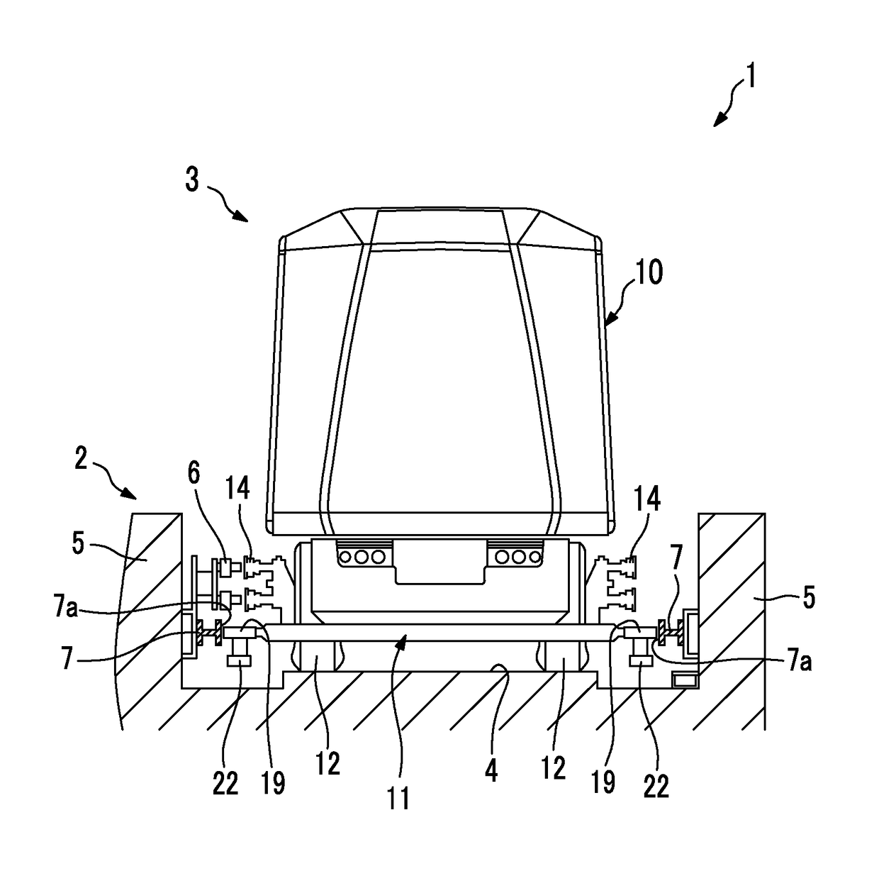
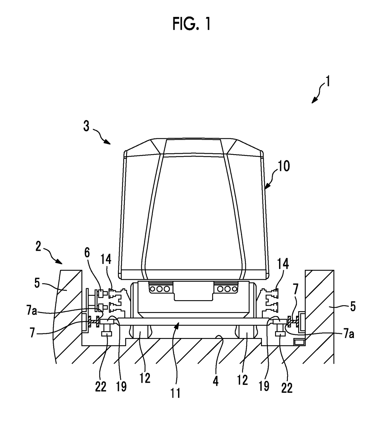
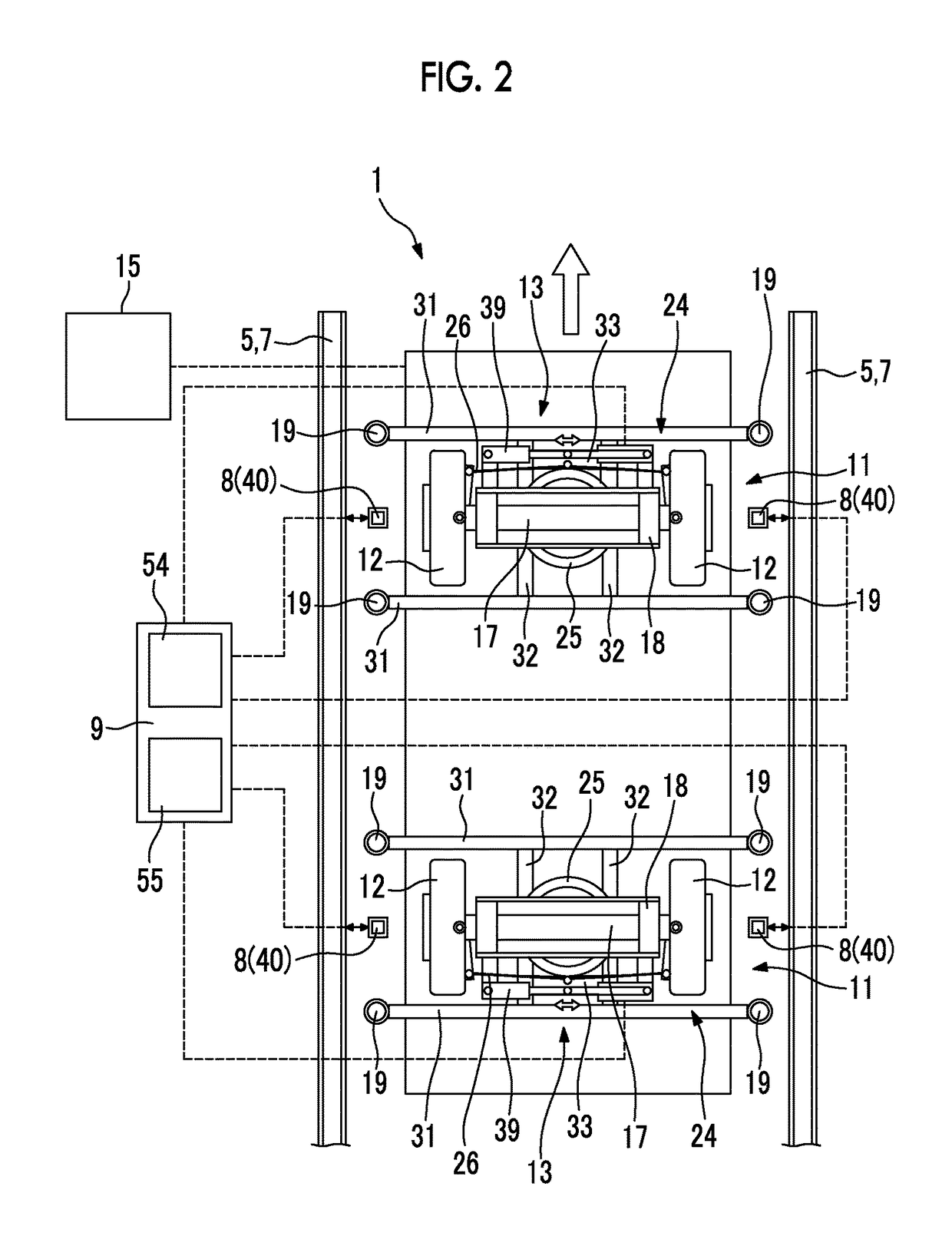
[0039]As shown in FIGS. 1 and 2, the transport system 1 is formed of a so-called side guide type system including a vehicle 3, a track 2 on which the vehicle 3 travels, an operational control unit 15 that allows the vehicle 3 to travel according to an operational plan by controlling supply of power to the vehicle 3, and guide rails 7 that guide the vehicle 3 on both left and right sides of the track 2 in a width direction and are made of steel. In the side guide type system, the vehicle 3 travels while being guided on both left and right sides in a width direction.

[0040]Here, a longitudinal direction is defined while the front side of the vehicle 3 in a traveling direction is simply defined as the front side, and a transverse direction is defined while the right side of the vehicle, which faces the front side, is def...

second embodiment

[0095]Next, a transport system 1A according to a second embodiment of the invention will be described.

[0096]Components, which are common to the first embodiment, are denoted by the same reference numerals as those of the first embodiment and the detailed description thereof will be omitted.

[0097]The transport system 1A of this embodiment includes a structure 82 instead of the guide faces 7a of the guide rails, and position detection parts 80 of the transport system 1A are different from those of the first embodiment.

[0098]As shown in FIG. 8, a pair of (left and right) position detection parts 80 are mounted on a support frame 24 of a running device 11 or a vehicle body 10 by brackets (not shown) or the like so as to be disposed between two (left and right) running wheels 12 on a line segment parallel to the rotation axis of an axle 17.

[0099]Each of the position detection parts 80 includes a sensor 81 that detects a distance between the structure 82 and itself. In this embodiment, th...


PUM


Abstract

A vehicle includes running wheels traveling on traveling road surfaces of tracks; a pair of position detection parts disposed at an interval in a width direction that output signals by detecting a distance from measured objects; a control unit controlling the amount of steering of the running wheels according to the signals from the position detection parts; and a steering mechanism steering the running wheels via the control unit. Each of the position detection parts outputs a signal having characteristics such that the output increases as the distance from the measured objects increases while an output change ratio is decreased in a range wherein the distance from the measured objects is not less than a predetermined value, and is configured such that, when the distance between one position detection part and the measured object is decreased, the distance between the other position detection part and the measured object is increased.

Description

RELATED APPLICATIONS[0001]The present application is National Phase of International Application No. PCT / JP2013 / 051866 filed Jan. 29, 2013, the disclosure of which is hereby incorporated by reference herein in its entirety.TECHNICAL FIELD[0002]The present invention relates to a vehicle that can be automatically steered, and a track transportation system that includes a track on which the vehicle travels.BACKGROUND ART[0003]A track transportation system in which a vehicle travels on a track by using running wheels formed of rubber tires and guide wheels of the vehicle are guided by guide rails is known as new means of transportation other than a bus and a railroad. This track transportation system is generally called a new transport system or an Automated People Mover (APM).[0004]Further, there are a side guide method and a center guide method as a steering method in this kind of new transport system. All of these steering methods are a so-called passive steering method in which a ve...

Claims


Application Information

Patent Timeline
Patent Type & Authority Patents(United States)
IPC IPC(8): G05D1/00B61B13/00G05D1/02B61L3/00B61L27/04B61L23/04B61B13/04B61L25/02
CPCB61L3/00B61B13/00B61B13/04B61L27/04G05D1/021B61L23/041B61L2201/00B61L25/026
Inventor MAEYAMA, HIROYUKISUZUKI, TAKAHIROKATAHIRA, KOUSUKE
Owner MITSUBISHI HEAVY IND ENG LTD
Why Eureka
Try Eureka