
Data center air handling unit including uninterruptable cooling fan with weighted rotor and method of using the same

a technology of air handling unit and uninterruptable power supply, which is applied in the field of data center air handling unit including uninterruptable power supply with weighted rotor, can solve the problems of uninterruptible power supply, unstandardized, accessible and relatively convenient position of units, and approximately 15 seconds between, so as to prevent damage to electrical equipment and prevent damage to said electronic equipmen

Active Publication Date: 2017-11-21
SWITCH COMM GRP LLC
View PDF225 Cites 18 Cited by
  • Summary
  • Abstract
  • Description
  • Claims
  • Application Information

AI Technical Summary

Benefits of technology

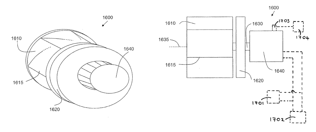
This patent describes a method and apparatus for preventing damage to electrical equipment that is cooled by a cooling unit. The cooling unit is powered by a grid power source and a back-up generator. The fan of the cooling unit rotates at a specific speed to create airflow. When there is no grid power, the fan continues to rotate using the back-up generator to maintain airflow for a certain period of time. This prevents damage to the electronic equipment and ensures continued cooling.

Problems solved by technology

These units, however, are not located in standardized, accessible and relatively convenient positions relative to the facility should any of the units need to be accessed and / or removed for repair or replacement.
Further, these units are not themselves created using an intentionally transportable design.
However, there is typically a period of approximately 15 seconds between the power going down and the back-up generators coming on line.
These uninterruptible power supplies are on-site at the data center.
However, providing the uninterruptible power supplies for a data center is very expensive, since not only are the power supplies expensive, but valuable floor space is required within the data center.
Furthermore, the uninterruptable cooling fans may also be configured for generation of electricity to power a control system associated therewith during a power outage until back-up generators come on-line.

Method used


Image

  • Data center air handling unit including uninterruptable cooling fan with weighted rotor and method of using the same
  • Data center air handling unit including uninterruptable cooling fan with weighted rotor and method of using the same
  • Data center air handling unit including uninterruptable cooling fan with weighted rotor and method of using the same

Examples


Embodiment Construction

[0028]Data center or co-location facility designs and methods of making and using the same are described, and specifically a data center air handling unit including uninterruptable cooling fan with weighted rotor.

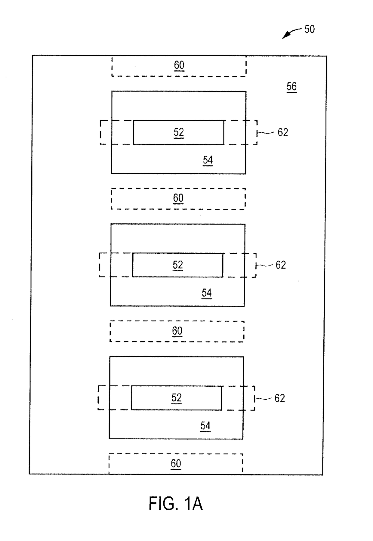
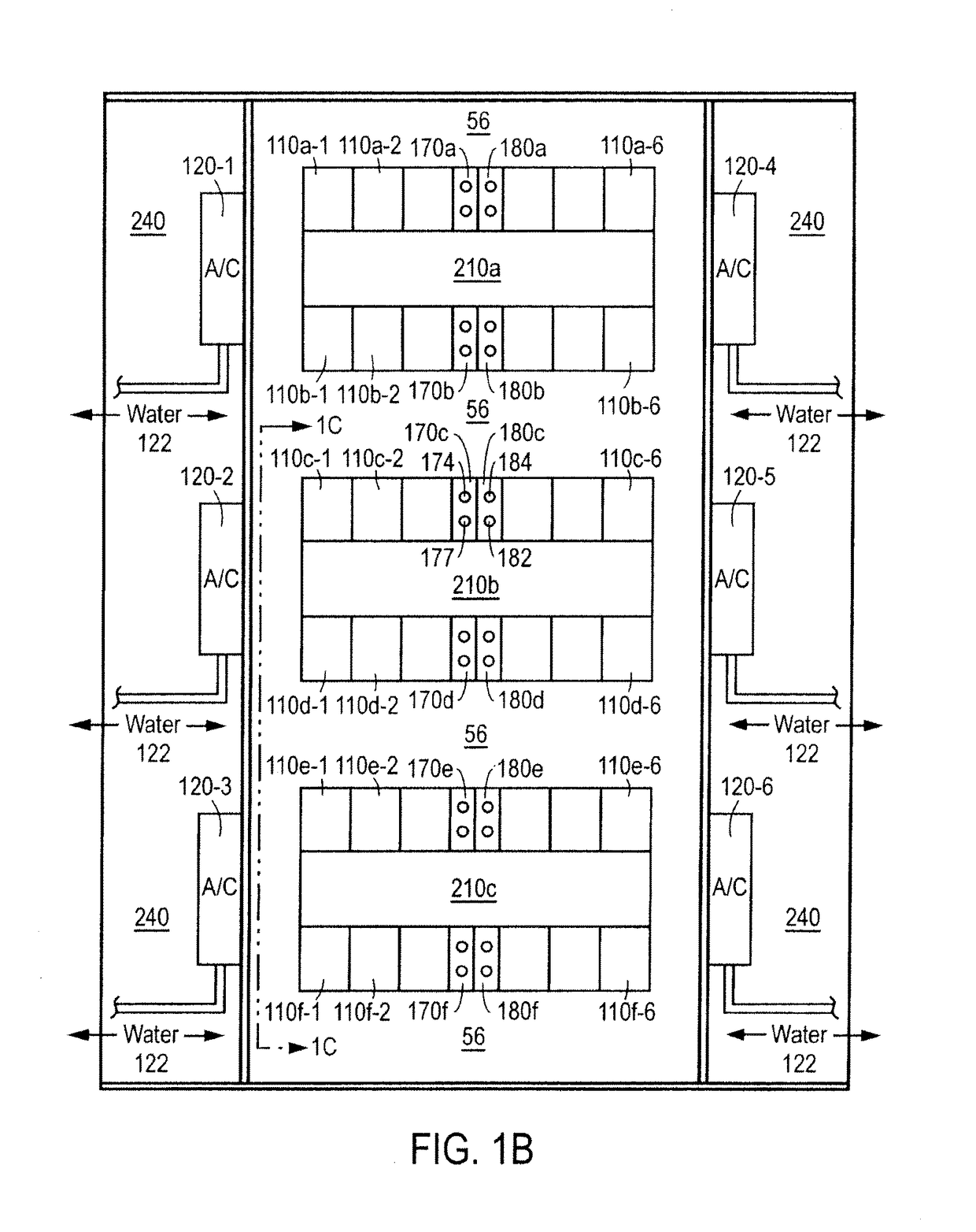
[0029]FIG. 1A illustrates a floor design used in the data center or co-location facility. The preferred embodiment discussed herein uses parallel rows of equipment configured back-to back so that each row of equipment generally forces the heat from the electronic equipment towards a hot aisle, thus also establishing a cold aisle in the front of the equipment. The cold aisles in FIG. 1A are illustrated at the dotted line block 60, wherein the hot aisles are illustrated at the dotted line block 62. One feature is the provision for marking the floor 50 to explicitly show the various areas of the facility. As illustrated, the hot aisle 62 has a central area 52 that is tiled, painted, taped or otherwise marked to indicate that it is center area of the hot aisle 62, also referred...


PUM


Abstract

Described herein is an air handling unit for use in an integrated data center that provides for efficient cooling, wherein the air handling unit includes one or more uninterruptable cooling fans each with a weighted rotor for providing uninterrupted cooling during a power outage until back-up generators come on-line, and a method of using the same. The uninterruptable cooling fan rotors are configured to store sufficient energy as rotational kinetic energy. Furthermore, the uninterruptable cooling fans may also be configured for generation of electricity to power a control system associated therewith during a power outage until back-up generators come on-line.

Description

[0001]This application is a continuation-in-part of and claims priority to U.S. Utility application Ser. No. 12 / 384,102 entitled “Data Center Air Handling Unit” filed on Mar. 30, 2009, which application claims priority to U.S. Provisional Application No. 61 / 040,636 entitled “Electronic Equipment Data Center or Co-Location Facility Designs and Methods of Making and Using the Same,” filed on Mar. 28, 2008, and is also a continuation-in-part and claims priority to U.S. Utility application Ser. No. 12 / 138,771 entitled “Electronic Equipment Data Center or Co-location Facility Designs and Methods of Making and Using the Same” filed Jun. 13, 2008, which application claims priority to U.S. Provisional Application Ser. No. 60 / 944,082 entitled “Electronic Equipment Data Center or Co-location Facility Designs and Methods of Making and Using the Same” filed Jun. 14, 2007, which applications are expressly incorporated by reference herein.BACKGROUNDField of the Related Art[0002]The embodiments de...

Claims


Application Information

Patent Timeline
Patent Type & Authority Patents(United States)
IPC IPC(8): F24F3/00G06F1/20H05K7/20
CPCG06F1/20H05K7/20172H05K7/20745
Inventor ROY, ROB
Owner SWITCH COMM GRP LLC
Learn More