Coil unit and electric vehicle

a coil unit and electric vehicle technology, applied in the direction of electric vehicles, transformers/inductance circuits, cores/yokes, etc., can solve the problems of heavy material, heavy material, and large magnetic flux guide unit, and achieve the effect of reducing the cost of electric vehicles

Active Publication Date: 2017-11-21
CONDUCTIX WAMPFLER
View PDF7 Cites 4 Cited by
  • Summary
  • Abstract
  • Description
  • Claims
  • Application Information

AI Technical Summary

Benefits of technology

[0008]A coil unit and electric unit as disclosed herein make possible the safe use of the

Problems solved by technology

The ferrites, separated from one another, worsen the magnetic flux guidance and thus the coupling between the transformer parts.
With the known coil units, the disadvantage is that the magnetic flux guide unit, as a rule, is made of a massive, rigid, and heavy material, for example, a ferrite plate.
Since the coil unit is usually arranged, parallel to the surface, on the bottom of the vehicle

Method used


Image

  • Coil unit and electric vehicle
  • Coil unit and electric vehicle
  • Coil unit and electric vehicle

Examples


Embodiment Construction

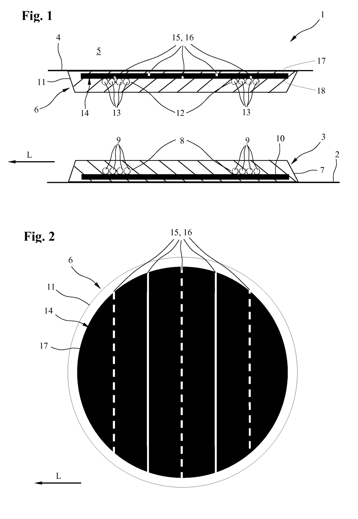
[0027]FIG. 1 shows, schematically, a lateral sectional view of an energy transfer device 1 for the inductive transfer of electrical energy between a primary coil unit 3, installed on a lane bottom 2, which is, in fact, known, and a secondary coil unit 6 in accordance with the invention, placed on a vehicle bottom 4 of an electric vehicle 5. The longitudinal and forward traveling direction of the electric vehicle 5 is marked with an arrow L in FIG. 1.

[0028]The primary coil unit 3 thereby comprises, in a manner which is, in fact, known, a primary coil housing 7 with a primary coil 8 located therein, with primary coil windings 9 and a primary coil-flux guide unit 10.

[0029]The secondary coil unit 6, which is also only designated, below, as the coil unit 6, has—in a manner which is, in fact, known—a housing 11 with a coil 12, integrated therein, with coil windings 13. In order to attain as good as possible a guidance of the magnetic flux for the inductive energy transfer, the coil unit 6...


PUM


Abstract

A coil unit for an electric vehicle for the inductive transfer of electrical energy between the coil unit and a stationary charging station. The coil unit includes at least one coil and a flux guide unit for guiding a magnetic flux occurring during operation of the coil. Also disclosed is an electric vehicle having a coil unit for the inductive transfer of electrical energy between a secondary coil of the coil unit and a primary coil of a charging station. The disclosed coil solves the problem of allowing the safe use of the inductive electrical energy transfer in electric vehicles, in particular motor vehicles, by proposing a coil unit, in which the flux guide unit has material weakenings, and an electric vehicle having such a coil unit.

Description

FIELD OF THE INVENTION[0001]The invention concerns a coil unit and an electric vehicle.BACKGROUND OF THE INVENTION[0002]In the area of the transfer of inductive energy to movable consumers, for example, electric land vehicles, such as automobiles or trucks, a method is known for charging its vehicle battery via a stationary primary coil of a charging station and a secondary coil located on the bottom of the vehicle. The primary coil is thereby located on or in the traveling lane, for example, on publicly accessible parking lots, charging areas of filling stations, or in the garage of the owner of the vehicle. For the charging operation, the electric vehicle is driven over the primary coil, so that the secondary coil that is located in the vehicle is aligned on the primary coil.[0003]DE 10 2009 033 236 A1 discloses an example for this, in which the secondary coil is located, together with a ferrite plate as a flux guide unit, in a housing on the bottom of an electric vehicle.[0004]DE...

Claims


Application Information

Patent Timeline
IPC IPC(8): H02J7/00B60L11/18H01F27/42H01F3/00H02J7/14
CPCH01F3/00B60L11/182Y02T90/14Y02T10/7072Y02T90/122Y02T10/7005B60L53/12Y02T10/70Y02T90/12
Inventor WECHLIN, MATHIASASSELIN, PASCALGREEN, ANDREW
Owner CONDUCTIX WAMPFLER
Why Eureka
Try Eureka