Cavopulmonary viscous impeller assist device and method

a technology of viscosity and assist device, which is applied in the field of cavopulmonary viscous impeller assist device and method, can solve the problems of inability to meet the conditions of survival, remain problematic, notorious for instability and mortality, and patients with univentricular fontan circulation are at high risk for late fontan failure and attrition

Active Publication Date: 2017-11-28
INDIANA UNIV RES & TECH CORP
View PDF121 Cites 5 Cited by
  • Summary
  • Abstract
  • Description
  • Claims
  • Application Information

AI Technical Summary

Benefits of technology

[0018]It is a further aspect of some embodiments to provide a permanent Fontan pump which will afford the opportunity to address right / left lung blood flow disparity;

Problems solved by technology

Until recently this condition was not compatible with survival.
While these procedures offer hope for survival, they remain problematic and notorious for instability and mortality.
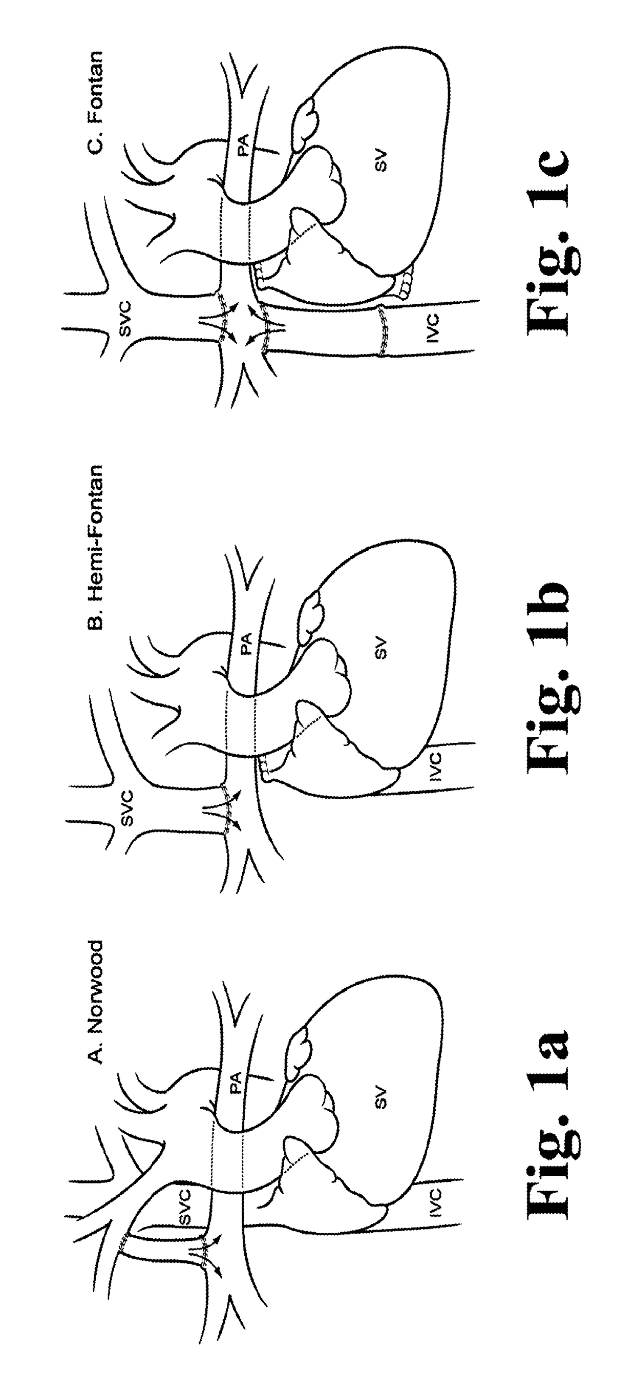
Patients with a univentricular Fontan circulation are therefore at high risk for late Fontan failure and attrition.
The insidious complications of chronically reduced preload include late ventricular diastolic dysfunction, and poor systemic tissue perfusion.
Similarly, although the use of inotropic support may improve myocardial contractility, this is of marginal impact in an insufficiently filled ventricle.
Heart transplantation is a poor end-stage option: Transplantation carries morbidity of its own, and the donor pool is limited.
This has limitations, however, as one-way flow devices will cause undesirable back-pressure elevation in the opposing vena caval territory.
Although in theory this is possible, the 3-way vascular configuration is not the preferred hemodynamic pathway in an unsupported Fontan circulation.

Method used


Image

  • Cavopulmonary viscous impeller assist device and method
  • Cavopulmonary viscous impeller assist device and method
  • Cavopulmonary viscous impeller assist device and method

Examples


Embodiment Construction

[0033]For the purposes of promoting an understanding of the principles of the invention, reference will now be made to the embodiments illustrated in the drawings and specific language will be used to describe the same. It will nevertheless be understood that no limitation of the scope of the invention is thereby intended, such alterations and further modifications in the illustrated device, and such further applications of the principles of the invention as illustrated therein being contemplated as would normally occur to one skilled in the art to which the invention relates. At least one embodiment of the present invention will be described and shown, and this application may show and / or describe other embodiments of the present invention. It is understood that any reference to “the invention” is a reference to an embodiment of a family of inventions, with no single embodiment including an apparatus, process, or composition that should be included in all embodiments, unless otherw...


PUM


Abstract

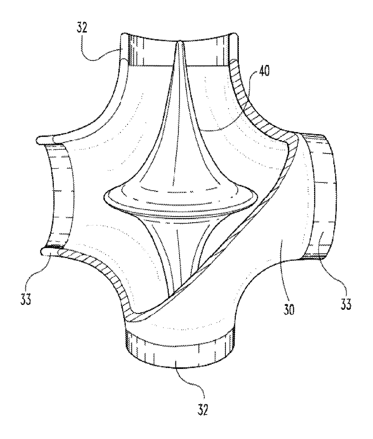
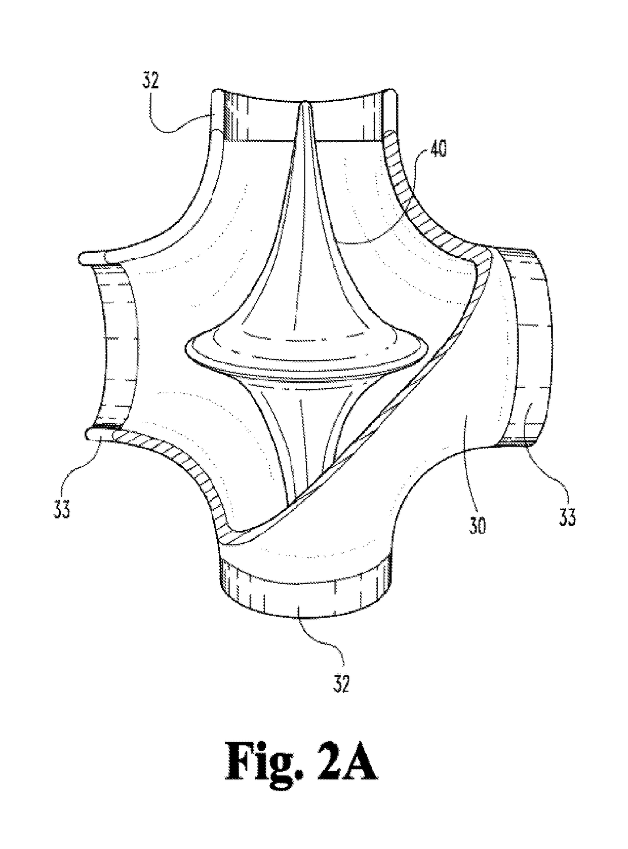
A bearingless and sealless rotary blood pump is disclosed which provides multidirectional flow intended to provide low-pressure, high-volume right-sided partial assist circulatory support in a univentricular Fontan circulation on a permanent basis. The pump includes a housing and an impeller suspended in the center of the housing. The housing incorporates flow optimization features between inlet and outlet ends, as well as with the impeller surface. Large fluid gaps maintained between impeller and housing eliminate any potential for blood flow obstruction. The impeller contains some motor components. It includes a central stator and surrounding rotor. The motor includes a brushless DC outrunner electrical motor design. An electromagnetic stator core is surrounded by a circumferential passive magnetic ring. The rotor is further levitated about the stator spindle by a plurality of axially and radially located passive magnetic and hydrodynamic journal bearings on both ends of the spindle. The rotor is bearingless and sealless. During impeller rotation, blood entering the space between the rotor and stator is induced to flow by centrifugal pumping action and the fluid film separates the stator hydrodynamic bearings from the rotor so that there is no direct mechanical contact between the rotor and stator.

Description

CROSS REFERENCE TO RELATED APPLICATIONS[0001]This application claims the benefit of priority to U.S. Provisional Patent Application Ser. No. 61 / 566,616, filed Dec. 3, 2011, titled CHRONIC CAVOPULMONARY ASSIST DEVICE AND METHOD, and U.S. Provisional Patent Application Ser. No. 61 / 611,947, filed Mar. 16, 2012, titled CAVOPULMONARY VISCOUS IMPELLER ASSIST DEVICE AND METHOD, both of which are incorporated herein by reference.FIELD OF THE INVENTION[0002]Various embodiments of the invention relate generally to the field of pumps including blood pumps, including non-positive displacement pumps of rotary design, and including those suitable for permanent implantation in animals for use in circulatory support.BACKGROUND OF THE INVENTION[0003]Some children are born missing half their heart. Known as single ventricle heart disease, it is the leading cause of death in children less than one year of age from any structural birth defect. One common anatomic variant is Hypoplastic Left Heart Syndr...

Claims


Application Information

Patent Timeline
Patent Type & Authority Patents(United States)
IPC IPC(8): A61M1/10A61M1/12A61M60/165A61M60/232A61M60/422A61M60/508A61M60/82A61M60/871
CPCA61M1/1036A61M1/101A61M1/1015A61M1/1017A61M1/127A61M1/1031A61M1/1086A61M1/122A61M1/125A61M1/1029A61M60/824A61M60/82A61M60/422A61M60/812A61M60/232A61M60/878A61M60/35A61M60/804A61M60/861A61M60/871A61M60/508A61M60/165A61M60/419A61M60/148
Inventor RODEFELD, MARK D.
Owner INDIANA UNIV RES & TECH CORP
Why Eureka
Try Eureka