Motor vehicle and rear-end module therefor

a rear-end module and motor vehicle technology, applied in the field of motor vehicles, can solve the problems of unwanted steps along the load path, unfavorable reliable force transmission, and risk of destruction of such screw connections, and achieve the effect of stiffening the vehicle body

Active Publication Date: 2017-11-28
AUDI AG
View PDF38 Cites 4 Cited by
  • Summary
  • Abstract
  • Description
  • Claims
  • Application Information

AI Technical Summary

Benefits of technology

[0016]The support structure advantageously has receptacles for fastening chassis components and damper elements. It has also proven advantageous to configure the support structures as extruded parts, in particular made of aluminum or an aluminum alloy. The support str...

Problems solved by technology

A disadvantage in such a configuration of the rear section of the vehicle is that the secondary load path is formed by a beam that is contributed by the body in white and by an only subsequently mounted rear axle bracket.
This results in unwanted steps along the load path, wherein the occurring forces have to be transmitted via the screw connections.
As a result it is not always ensured that in the event of a rear impact, forces are directly introduced via the secondary load path into the vehicle floor.
This poses the risk of de...

Method used


Image

  • Motor vehicle and rear-end module therefor
  • Motor vehicle and rear-end module therefor
  • Motor vehicle and rear-end module therefor

Examples


Embodiment Construction

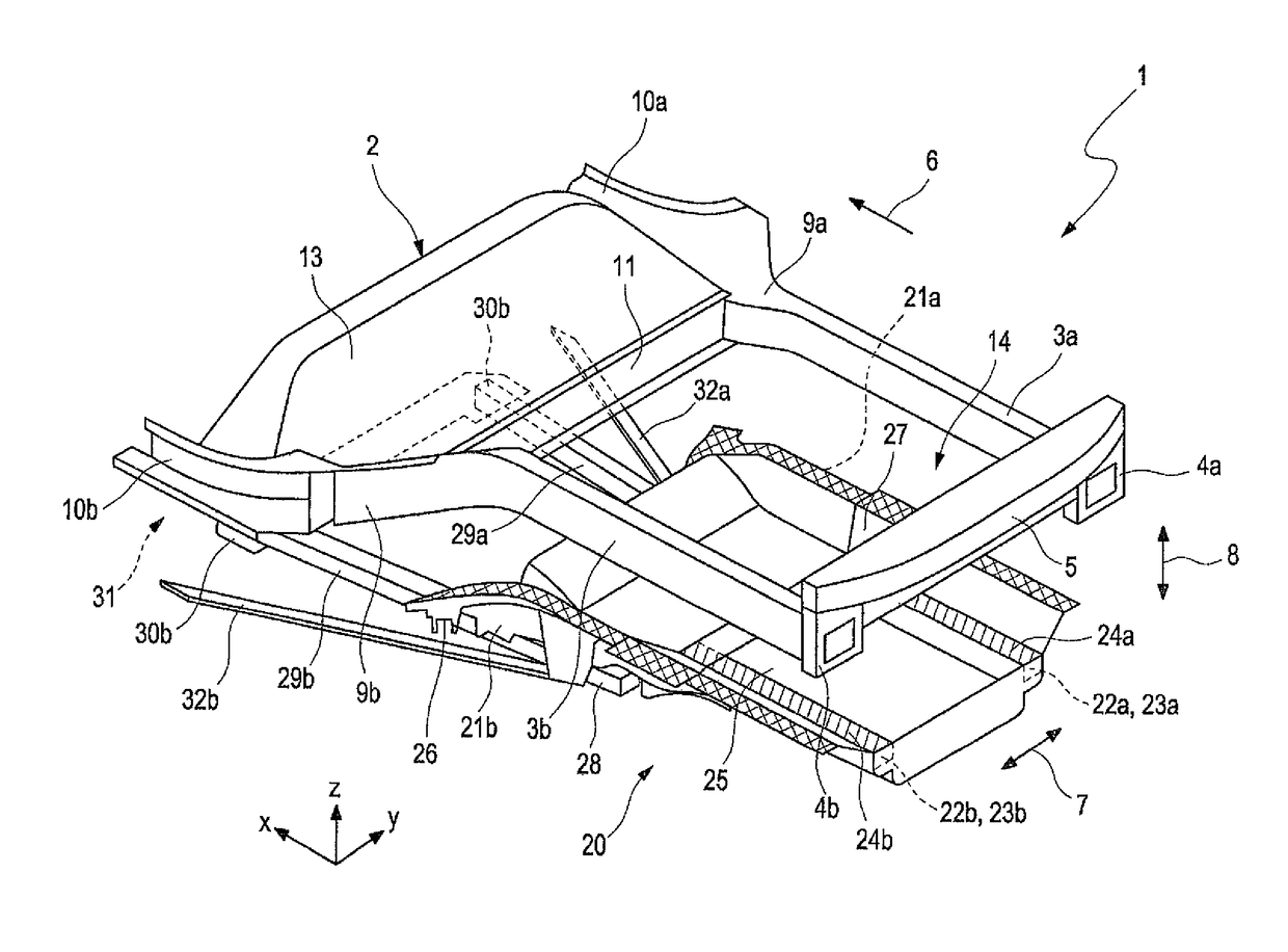
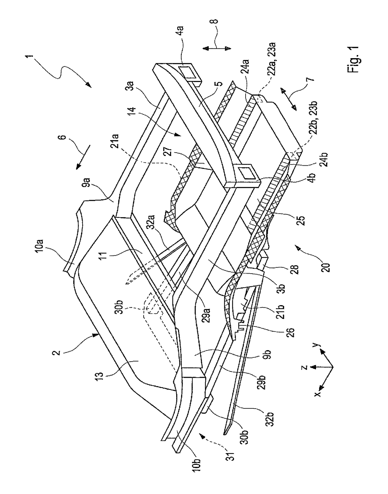
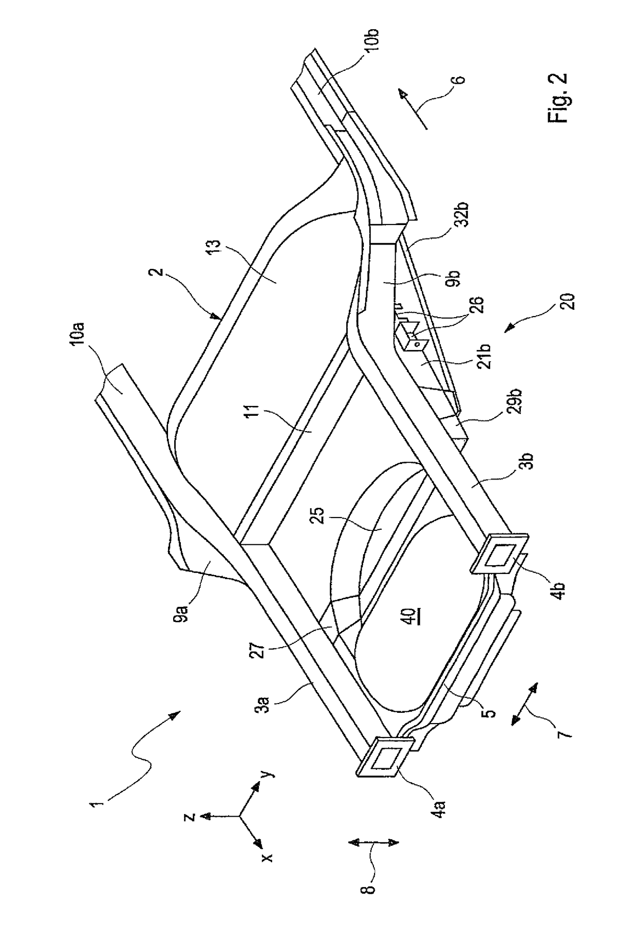
[0033]A motor vehicle 1 according to the invention has a vehicle body 2. In FIGS. 1 to 5 only a part of the structure in particular a rear-body structure of such a vehicle body 2 is shown in the following. The vehicle body 2 has two rear longitudinal members 3a, 3b, which are a part of the body-in white. The longitudinal members 3a, 3b are for example box-shaped and each have a rear side end 4a, 4b. In the region of the rear side ends 4a, 4b the longitudinal members 3a, 3b are connected by means of a rear cross member 5.

[0034]For the following description the direction indicated by arrow 6 is the driving direction of the vehicle or the longitudinal axis of the vehicle (x-axis). The double arrow 7 indicates the transverse direction of the vehicle. The vehicle transverse direction hereby usually corresponds to a y-direction. The double arrow 8 indicates a vertical direction (z-direction) of the vehicle. At a front end with respect to the driving direction 6 the longitudinal members 3,...


PUM


Abstract

A motor vehicle includes a body, which body has at least two rear longitudinal members each forming a primary load path for collision forces, wherein the motor vehicle has a rear-end module that can be pre-assembled as a sub-assembly, which rear-end module can be connected to the body as part of the vehicle assembly after the completion of the body-in-white and has at least a supporting structure for fastening chassis components of a rear wheel suspension and a beam structure extending from the supporting structure toward the motor-vehicle rear for absorbing collision forces, wherein the supporting structure and the beam structure form at least one second load path for collision forces.

Description

CROSS-REFERENCES TO RELATED APPLICATIONS[0001]This application is the U.S. National Stage of International Application No. PCT / EP2015 / 000513, filed Mar. 6, 2015, which designated the United States and has been published as International Publication No. WO 2015 / 144289 and which claims the priority of German Patent Application, Serial No. 10 2014 004 166.2, filed Mar. 22, 2014, pursuant to 35 U.S.C. 119(a)-(d).BACKGROUND OF THE INVENTION[0002]The invention relates to a motor vehicle according to the preamble of claim 1 and a rear-end module therefore according to the preamble of claim 17.[0003]From DE 102012205967 a support-structure assembly is known, which is provided for connection with a box-type frame of a motor vehicle, wherein individual components of the support structure have mounts for chassis components.[0004]From DE10 2006040837 A1 it is known to directly fasten control arms of a wheel-guiding multilink arrangement with their side that faces away from the associated wheel ...

Claims


Application Information

Patent Timeline
IPC IPC(8): B62D21/15B60K15/063B62D25/02B62D24/00B62D25/20B62D21/11B62D29/00B62D21/02B62D27/02
CPCB62D21/152B60K15/063B62D21/02B62D21/11B62D25/025B62D25/2027B62D29/008B62D24/00B62D27/026B60K2015/0638B62D21/155B62D25/087B62D43/00
Inventor LANGHOFF, HANS-JURGENRUGIES, STEFANURBAN, TOBIASDECKER, DENNISENDERLE, SEBASTIANSCHLICHTER, PASCAL
Owner AUDI AG
Why Eureka
Try Eureka