Wall sheathing with passive energy dissipation

a technology of passive energy dissipation and wall sheathing, which is applied in the field of wall sheathing, can solve the problems of limited displacement capacity, limited energy dissipation of wall panels, and increase ductility, and achieve the effect of increasing passive energy dissipation

Active Publication Date: 2017-11-28
TIPPING STEVEN B
View PDF37 Cites 5 Cited by
  • Summary
  • Abstract
  • Description
  • Claims
  • Application Information

AI Technical Summary

Benefits of technology

[0010]The present invention provides a wall sheathing that yields and deforms when subjected to external excitations such as wind or earthquake, thus protecting the connections that fasten the sheathing to the stud. By so doing, the present invention provides increased passive energy dissipation as measured by the fullness and length of its hysteresis loop.

Problems solved by technology

Also, as the displacement capacity of the product or system increases (length of hysteresis loop), its ductility increases.
This being the case, when subjected to horizontal shear forces induced by wind or earthquake, walls sheathed with plywood panels tend to rack rather than deform, resulting in the nails bending and pulling out of wood studs or the self-tapping screws gouging an elongated hole in the cold-formed steel studs.
Both of these general failure modes result in limited displacement capacity and limited energy dissipation of the wall panel.
Both of these hysteresis loops are pinched and have limited displacement capacity.
The primary failure mode of the sheet metal sheathing is gouging and tearing of the sheet steel at the fastener when subjected to tension loads and buckling when subjected to compression loads.
This failure mode results in limited displacement capacity and limited energy dissipation of the wall panel.
Similar to plywood sheathing, the sheet metal sheathing has a pinched hysteresis loop and therefore limited displacement capacity.
No information is available on the failure mode of the Sure-Board® panels.
However, a review of a typical hysteresis loop for a Sure-Board® test panel as illustrated in FIG. 6 shows the same pinched hysteresis loop and limited displacement capacity and limited energy dissipation as plywood and sheet metal sheathing—implying failure occurred at the fastener.
Typically, panel failure occurs at the connection point, resulting in limited displacement capacity and limited ability to dissipate energy when subjected to external excitations such as wind or earthquake.

Method used


Image

  • Wall sheathing with passive energy dissipation
  • Wall sheathing with passive energy dissipation
  • Wall sheathing with passive energy dissipation

Examples


Embodiment Construction

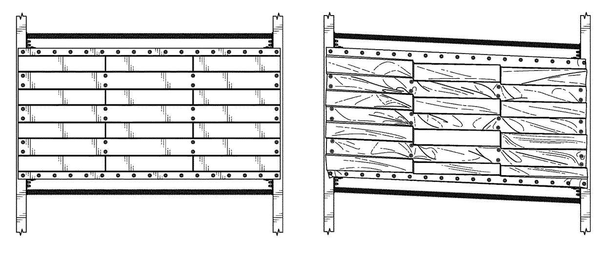
[0046]Many embodiments described below can be utilized as wall sheathing to resist external excitations such as wind or earthquake of light-framed wall structures.

[0047]I. Exemplary Shear Panel

[0048]In many embodiments, sheet metal is cold-formed to create a recurring corrugation pattern across the width of the sheet. This corrugation pattern is referred to as the sheet profile and consists of top flutes, bottom flutes, and webs as illustrated in FIG. 7.

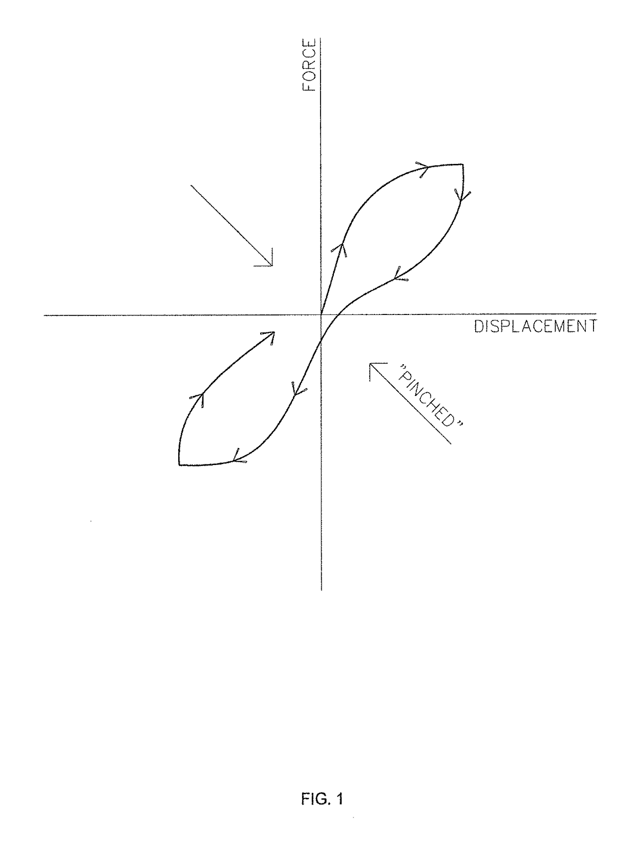
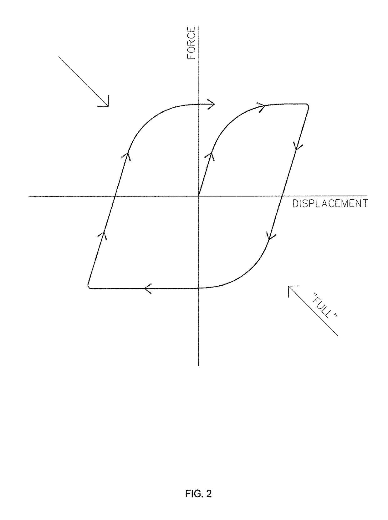
[0049]In many embodiments, the slope of the profile web, as defined by the angle (a) illustrated in FIG. 7, is set to insure that the top flutes deform laterally and yield at the end of the flute, as illustrated in FIG. 8, before any basic failure mode occurs thus providing a full hysteresis loop. Ideally, this angle would be set at 0°; however, shipping and handling of the product will, in all likelihood, necessitate that the angle be greater than 0°. It should be noted that as the angle increases, the stiffness of the flute increas...


PUM

PropertyMeasurementUnit
angleaaaaaaaaaa
yield strengthaaaaaaaaaa
angleaaaaaaaaaa

Abstract

A corrugated sheet metal wall sheathing for resisting external excitations such as wind or earthquake of light-framed wall structures. The sheathing has sheet profile proportioned to insure the top flutes deform laterally and yield at the end of the flute before the onset of any failure mode. A transverse slot in included in each top flute and adjacent web of the sheathing and spaced at intervals along the length of the sheathing.

Description

CROSS-REFERENCES TO RELATED APPLICATIONS[0001]This application claims the benefit of U.S. Provisional Application No. 61 / 970,342, filed Mar. 25, 2014, the entirety of which is incorporated by reference herein.BACKGROUND OF THE INVENTION[0002]This invention generally relates wall sheathing, particularly relates to wall sheathing for the design and construction of wind and seismic force-resisting systems used in building structures.[0003]In order to protect a structure such as a building and the people who may occupy or be in the vicinity of such structures, seismic force-resisting systems have been devised. The International Building Code (IBC) defines many of these systems, one being “light-framed walls sheathed with wood structural panels rated for shear resistance or steel sheets.” Light-framed walls are constructed with wood studs or cold-formed steel studs spaced at 16″ or 24″ on center.[0004]Wood structural panels rated for shear resistance include “plywood” and “OSB” (oriented...

Claims


Application Information

Patent Timeline
Patent Type & Authority Patents(United States)
IPC IPC(8): B32B3/10E04C2/32E04C2/26E04C2/08E04B2/56B32B3/26B32B15/04B32B7/08B32B3/28B32B3/24E04H9/02
CPCE04C2/324B32B3/28E04C2/08E04C2/322E04H9/02B32B3/266Y10T428/249923B32B3/10B32B7/08B32B15/04B32B2307/50B32B2607/00E04C2/26Y10T428/12361Y10T428/24314Y10T428/24322Y10T428/24331Y10T428/24669Y10T428/24694Y10T428/24719
Inventor TIPPING, STEVEN B.
Owner TIPPING STEVEN B
Why Eureka
Try Eureka