Radial annular mixed seal

A hybrid and ring-shaped technology, which is applied in the direction of engine seals, engine components, mechanical equipment, etc., can solve the problems that the airflow excitation problem cannot be fundamentally solved, the sealing gap self-adaptive adjustment is difficult, and the fluid excitation force has a large influence, etc. , to achieve the effect of turbulent flow resistance increase obviously, simple structure, avoid dynamic and static friction

Inactive Publication Date: 2011-10-05
SOUTHEAST UNIV
View PDF8 Cites 5 Cited by
  • Summary
  • Abstract
  • Description
  • Claims
  • Application Information

AI Technical Summary

Problems solved by technology

For the "axial seal", there are mainly the following problems: (1) Spiral flow, under the joint action of the fluid leakage flow along the axial direction and the high-speed rotation of the rotor, the spiral flow will inevitably appear in the seal cavity This is the main source of the current recognized airflow excitation force; (2) The pre-swirl has a great influence on the fluid excitation force, and the pre-swirl will appear at the inlet of the rotating mechanical seal, and the pre-swirl will increase the spiral flow phenomenon, thereby Large airflow excitation force is generated; (3) There is a contradiction between leakage and wear resistance; (4) It is difficult to adjust the sealing gap adaptively, and the axially arranged seal and gap adjustment need to be carried out in the circumferential direction, requiring the sealing block It can freely "expand" and "shrink", which brings great difficulties to the adaptive adjustment of the sealing gap
Practice has shown that this type of seal is particularly prone to seal jamming failures
Due to the existence of the above problems, the problem of airflow excitation cannot be fundamentally solved

Method used


Image

  • Radial annular mixed seal
  • Radial annular mixed seal
  • Radial annular mixed seal

Examples


Embodiment Construction

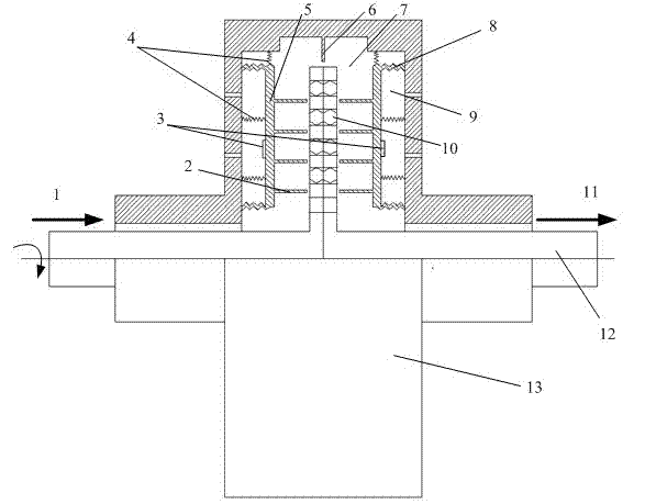
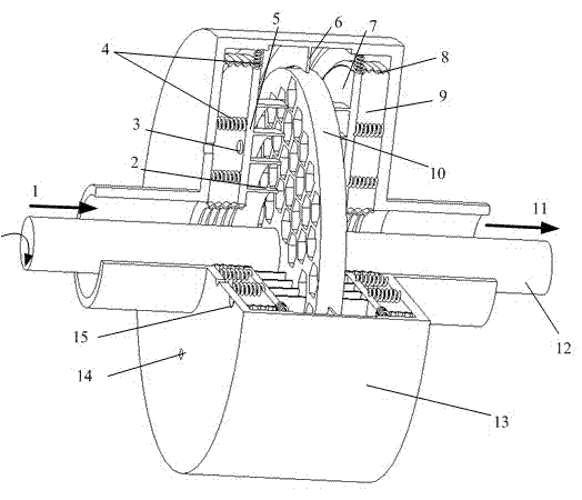
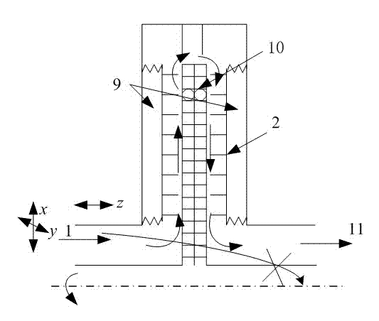
[0017] A radial annular hybrid seal, comprising: a rotor 12 and a seal sleeve 13 sleeved on the rotor 12, an adjustment plate 5 is arranged inside the seal sleeve 13, and the adjustment plate 5 passes through the corrugated joint 8 installed in the seal sleeve 13 Connected with the support spring 4 and the sealing sleeve 13, a pressure chamber 9 is formed between the adjusting plate 5 and the sealing sleeve 13, and a sealing cavity 7 is formed between the adjusting plate 5 and the honeycomb sealing disc 10 installed on the rotor 12, and the adjusting plate 5 is provided with an annular sealing tooth 2 and the annular sealing tooth 2 is located between the honeycomb sealing disc 10 and the regulating plate 5, an acceleration sensor 3 is provided on the regulating plate 5, and a pressure chamber exhaust hole 14 and Pressure chamber air inlet 15.

[0018] figure 1 As shown, a honeycomb sealing disc is designed on the rotating shaft, that is, honeycomb holes are set on the disc s...


PUM


Abstract

The invention discloses a radial annular mixed seal, which comprises a rotor and a sealing sleeve sleeved on the rotor, wherein a pressure cavity air outlet and a pressure cavity air inlet are formed on the sealing sleeve; an adjusting plate and a bellow section are arranged inside the sealing sleeve; one end of the bellow section is fixed on the sealing sleeve, and the other end of the bellow section is connected with the adjusting plate; and a pressure cavity is formed between the adjusting plate and the sealing sleeve. The radial annular mixed seal is characterized in that: a honeycomb sealing disc is arranged on the rotor and is positioned in the middle of the adjusting plate; and a sealing cavity is formed between the adjusting plate and the honeycomb sealing disc. By the radial annular mixed seal, axial flow of gas is changed into radial flow, axial spiral flow is eliminated, the leakage rate is greatly reduced compared with the common seal because the honeycomb sealing disc is arranged, a sealing gap has high adaptive adjusting capacity, the seal has long service life, the exciting force of the airflow in the seal is obviously reduced, and the airflow excitation is greatly reduced.

Description

technical field [0001] The invention relates to a sealing type applied in a rotary machine, in particular to a radial annular hybrid seal for a rotary machine. Background technique [0002] At present, reducing the leakage of the seal and improving the wear resistance of the seal have been the focus of people's attention. These two points can be regarded as the static characteristics (synergy) of the seal. In recent years, more and more attention has been paid to the sealing dynamic characteristics (vibration reduction) at home and abroad. This is because, with the improvement of working parameters, the exciting force generated by the fluid in the seal is getting bigger and bigger, and the harm to the safe operation of the unit is also getting bigger and bigger. For this reason, on the basis of the traditional sparse-tooth seal, by changing the structure of the seal itself, new types of seals such as honeycomb, brush, reverse swirl, damping, spiral groove, ladder, and mixin...

Claims


Application Information

Patent Timeline
IPC IPC(8): F16J15/16F16J15/40
Inventor 杨建刚张万福曹浩郭瑞孙丹
Owner SOUTHEAST UNIV
Why Eureka
Try Eureka