Sealing structure for dynamic and static gaps of rotating machine

A technology of sealing structure and rotating machinery, applied in the direction of engine sealing, mechanical equipment, machine/engine, etc., can solve the problems such as the inability to ensure safe and stable operation, the lack of control structure design of the seal, the inability to effectively control the leakage volume, etc., and achieve good control. Flow effect, stable control of leakage, effect of preventing tooth root breakage

Active Publication Date: 2010-09-15
DALIAN UNIV OF TECH
View PDF7 Cites 5 Cited by
  • Summary
  • Abstract
  • Description
  • Claims
  • Application Information

AI Technical Summary

Problems solved by technology

[0003] The current sealing structure, some of which have poor throttling effect and cannot effectively control the leakage; some are equipped with sealing rings in the dynamic and static gaps, which are easy to wear and have a short service life; some cannot guarantee safe and stable operation under large flow of working fluid; more importantly It is the gap seal of the pump, especially the gap seal of the nuclear main pump. The extreme working condition of backflow should be considered. Most of the seals have no structural design to control backflow.

Method used


Image

  • Sealing structure for dynamic and static gaps of rotating machine
  • Sealing structure for dynamic and static gaps of rotating machine
  • Sealing structure for dynamic and static gaps of rotating machine

Examples


Embodiment Construction

[0033] Below in conjunction with technical scheme and accompanying drawing, the present invention is described in detail by taking nuclear main pump as embodiment.

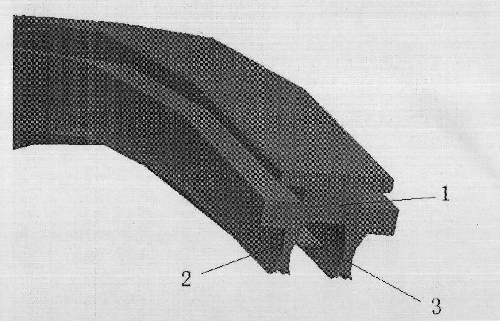
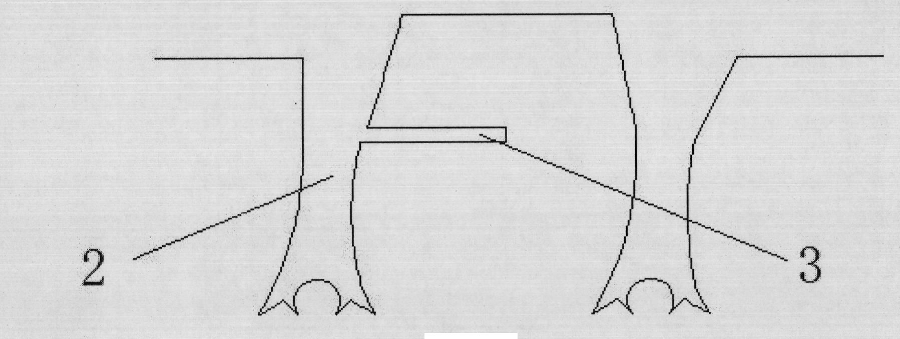
[0034] The sealing of the present invention is composed of two semicircular sealing rings, such as Figure 5 , can be installed in the dynamic and static clearance 4 between the impeller outlet and the guide vane of the nuclear main pump and the dynamic and static clearance 5 between the impeller inlet wheel cover and the inlet guide pipe, such as Image 6 , or installed in the gap between the heat shield and the shaft. The back arc of the sealing ring is installed along the sealing groove of the fixed part, and the inclined direction of the sealing teeth faces the direction of the incoming flow. The sealing structure of the present invention is mainly composed of a sealing ring 1 and a sealing tooth 2 .

[0035] The inner ring of the sealing ring can be provided with multiple sealing teeth, as shown in Figure 1...


PUM


Abstract

The invention relates to a sealing structure for dynamic and static gaps of a rotating machine. A transverse arm structure is arranged behind sealing tooth, and a claw-shaped structure is adopted on the top of the sealing tooth; the depth of a sealing cavity is increased, and the thicknesses of the root and the top of the sealing tooth are widened; oblique sealing tooth are applied; and both the windward side and the leeside of the sealing tooth adopt an arc surface modeling. The sealing structure is used for controlling the leakage of high-temperature and high-pressure fluid along the dynamic and static gaps and avoiding the condition that large-flow leakages influence the stable operation and the safe operation of parts of a next stage. Under the working medium conditions of high pressure, high temperature, high speed and large flow of a nuclear main pump, shown as a numerical simulation result, the sealing structure can reduce the leakage quantity by 13.8 percent compared with an ordinary straight-toothed labyrinth seal with the same gaps, can temporarily stabilize and control the leakage quantity under the extreme working condition of back flowing and has safety, durability and good throttling effect.

Description

technical field [0001] The invention belongs to the technical field of gap sealing, and relates to a sealing structure for a dynamic and static gap in a rotating machine. Background technique [0002] Gap sealing technology is used to control media leakage between rotating parts and stationary parts of rotating machinery. In order to ensure the safe and stable operation of the machine, a sufficient gap should be maintained between the rotating part and the stationary part, so a non-contact seal is selected to control the gap leakage flow. Non-contact sealing technology, that is, the fluid passes through the gap at the top of the sealing tooth, and the throttling is accelerated. In the large sealing chamber behind the sealing tooth, the kinetic energy of the fluid is converted into heat energy. The working medium passes through the sealing cavity, and the pressure gradually decreases to avoid the flow of the working medium. Large flow leaks. Common non-contact sealing forms...

Claims


Application Information

Patent Timeline
Patent Type & Authority Applications(China)
IPC IPC(8): F16J15/40F04D29/08
Inventor 王晓放张盟
Owner DALIAN UNIV OF TECH
Why Eureka
Try Eureka