Electrically conductive power transmission belt

a technology of electrical conductive and transmission belt, which is applied in the direction of electrostatic charges, mechanical devices, other domestic objects, etc., can solve the problems of rapid loss of anti-static effect, rapid loss of conductivity of belts, and damage to nearby electronic or electrical components or systems

Active Publication Date: 2017-11-28
THE GATES CORP
View PDF43 Cites 190 Cited by
  • Summary
  • Abstract
  • Description
  • Claims
  • Application Information

AI Technical Summary

Problems solved by technology

In use, a belt can rapidly lose conductivity from wear or breakdown of the conductive material component.
An unwanted side effect of such coatings is a decrease in the abrasion resistance of the fabric resulting in rapid loss of the anti-static effect during use.
The resulting abraded particles can be detrimental to nearby electronic or electrical components or systems.

Method used


Image

  • Electrically conductive power transmission belt
  • Electrically conductive power transmission belt
  • Electrically conductive power transmission belt

Examples


Embodiment Construction

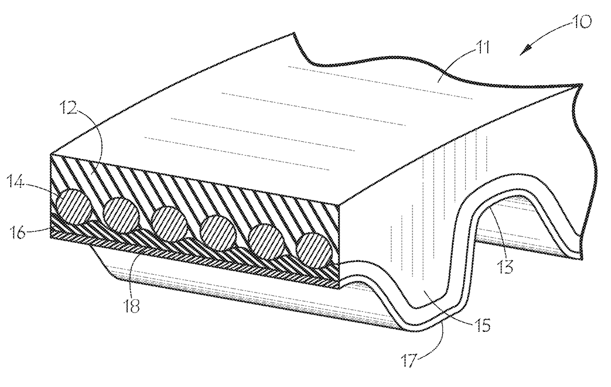
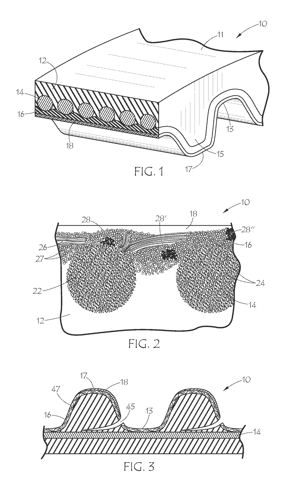
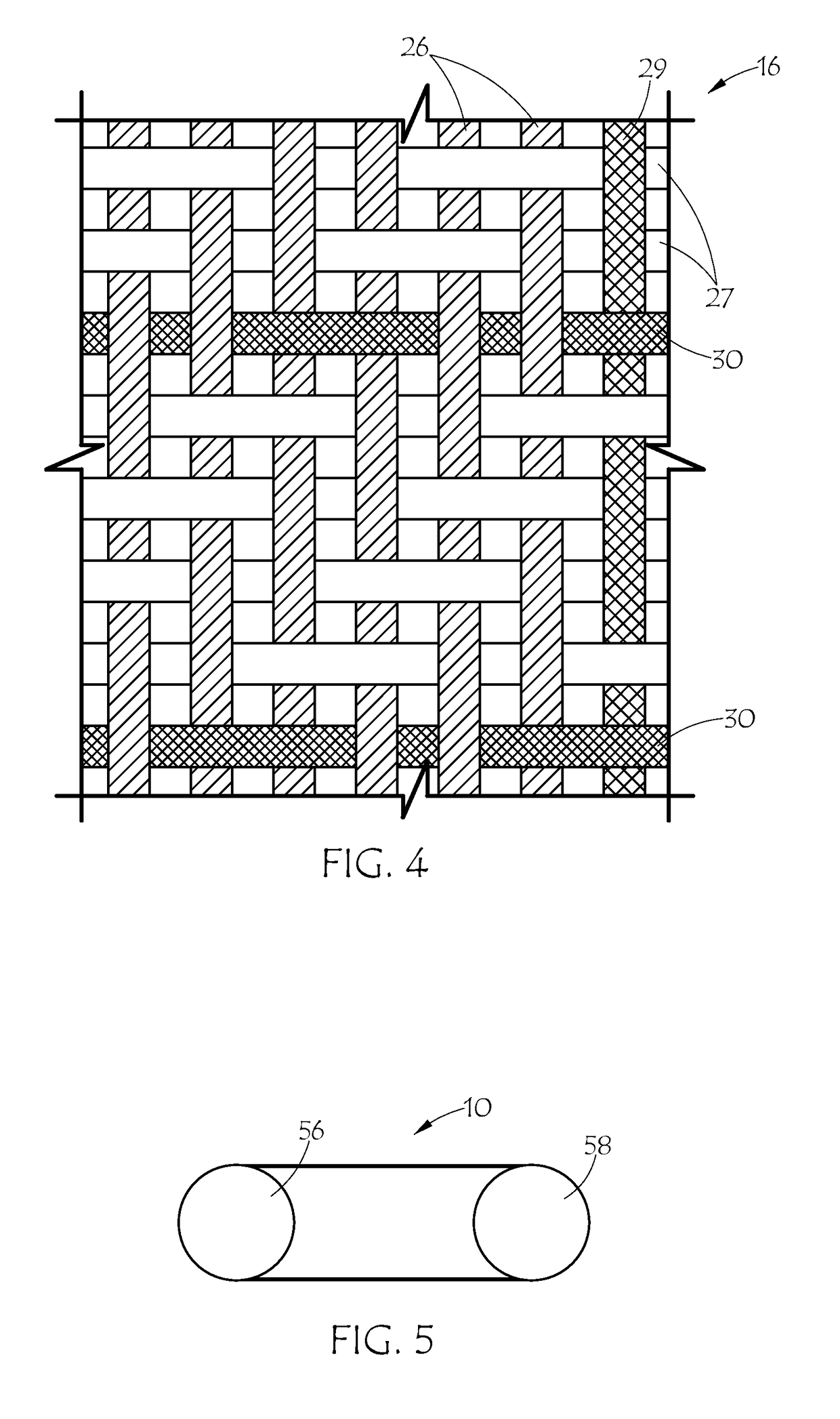
[0027]FIG. 1 shows an embodiment of the inventive conductive belt in the form of synchronous belt 10 with flat back side 11 and toothed side 17, which includes teeth 15 alternating with lands 13. The internal construction of synchronous belt 10 includes elastomeric body 12, tensile cord 14 embedded therein, fabric layer 16, and outer layer 18. Tensile cord 14 includes an electrically conductive material such as carbon fiber or metal wire. The cord may be a hybrid of the electrically conductive material with other non-conductive cord materials such as glass, aramid, PBO, or the like, provided the conductive material presents at the surface of the cord at least in a plurality of places. The fabric layer 16 is likewise conductive. The outer layer 18 is also conductive and may be a conductive thermoplastic film or a conductive thermoset coating which provides the belt with a surface conductivity suitable for at least dissipating static charges. The fabric layer 16 provides electrical co...


PUM

PropertyMeasurementUnit
surface resistivityaaaaaaaaaa
electrically conductiveaaaaaaaaaa
electrical continuityaaaaaaaaaa

Abstract

A belt made up of an elastomeric belt body, an electrically conductive tensile cord such as carbon fiber cord in a cord layer reinforcing the belt body, an outer layer of electrically conductive thermoplastic material such as polypropylene film, and an electrically conductive fabric layer residing between the tensile cord layer and the outer layer and providing electrical continuity between the outer layer and the tensile cord. An electrically conductive thread may be woven in the fabric and may present at both surfaces of the fabric and contact both the outer layer and the tensile cord to provide the electrical continuity there between.

Description

BACKGROUND OF THE INVENTION[0001]1. Field of the Invention[0002]This invention relates generally to electrically conductive power transmission belts, more particularly to static conductive timing belts, and specifically to a belt with conductive film, fabric, and tensile cord.[0003]2. Description of the Prior Art[0004]Drive belts are used for power transmission, motion control, transport applications, as well as for timing applications. Power transmission belts may be in the form of flat belts, toothed belts, V-belts, multi-v ribbed belts or other special profiles. They typically are electrically insulating and / or contain electrically insulating materials. It is sometimes desirable that the belts not retain electrostatic charges, i.e., that the belts have anti-static properties.[0005]Anti-static properties may be defined in various standards and generally include one or more of the following characteristics: surface resistance lower than 108 ohms; volume resistance lower than 109 oh...

Claims


Application Information

Patent Timeline
Patent Type & Authority Patents(United States)
IPC IPC(8): F16G1/10F16G5/20F16G5/08F16G1/28H05F3/00B29D29/08B29K75/00B29K105/08B29K105/10
CPCF16G1/10B29D29/08F16G1/28F16G5/08H05F3/00F16G5/20B29K2995/0005B29K2075/00B29K2105/0809B29K2105/10
Inventor THOMAS, CHRISTOPHER M.DUKE, JR., JOSEPH R.BIER, KARLA J.WILSON, CATHY PEAKE
Owner THE GATES CORP
Why Eureka
Try Eureka