System for loading elongated members such as tubes onto a conveyor for later processing

a technology of elongated members and conveyors, which is applied in the direction of drilling pipes, de-stacking articles, transportation and packaging, etc., can solve the problems of requiring human intervention in the use of overhead cranes, and affecting the safety of workers

Active Publication Date: 2017-12-05
VIDIR SOLUTIONS INC
View PDF11 Cites 4 Cited by
  • Summary
  • Abstract
  • Description
  • Claims
  • Application Information

AI Technical Summary

Benefits of technology

[0027]This arrangement may, in a more consistent manner, provide uniform lifting for the elongated members in an orientation which matches the first side of the second support surface so that the respective member may be properly moved from the elevator onto the second support surface.

Problems solved by technology

The laser cutting machine is itself relatively automated; however, typically a system for feeding members to the cutter machine is substantially manual.
Additionally, using the overhead crane still requires human intervention to arrange supports of the crane for holding the member around same.
Therefore, conventional manual loading presents a considerable safety risk to human operators / workers.

Method used


Image

  • System for loading elongated members such as tubes onto a conveyor for later processing
  • System for loading elongated members such as tubes onto a conveyor for later processing
  • System for loading elongated members such as tubes onto a conveyor for later processing

Examples


Embodiment Construction

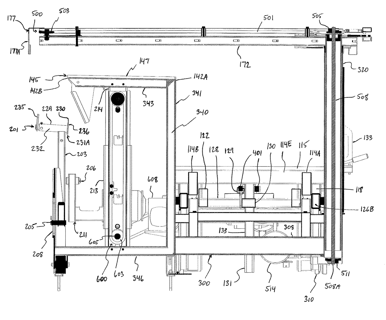
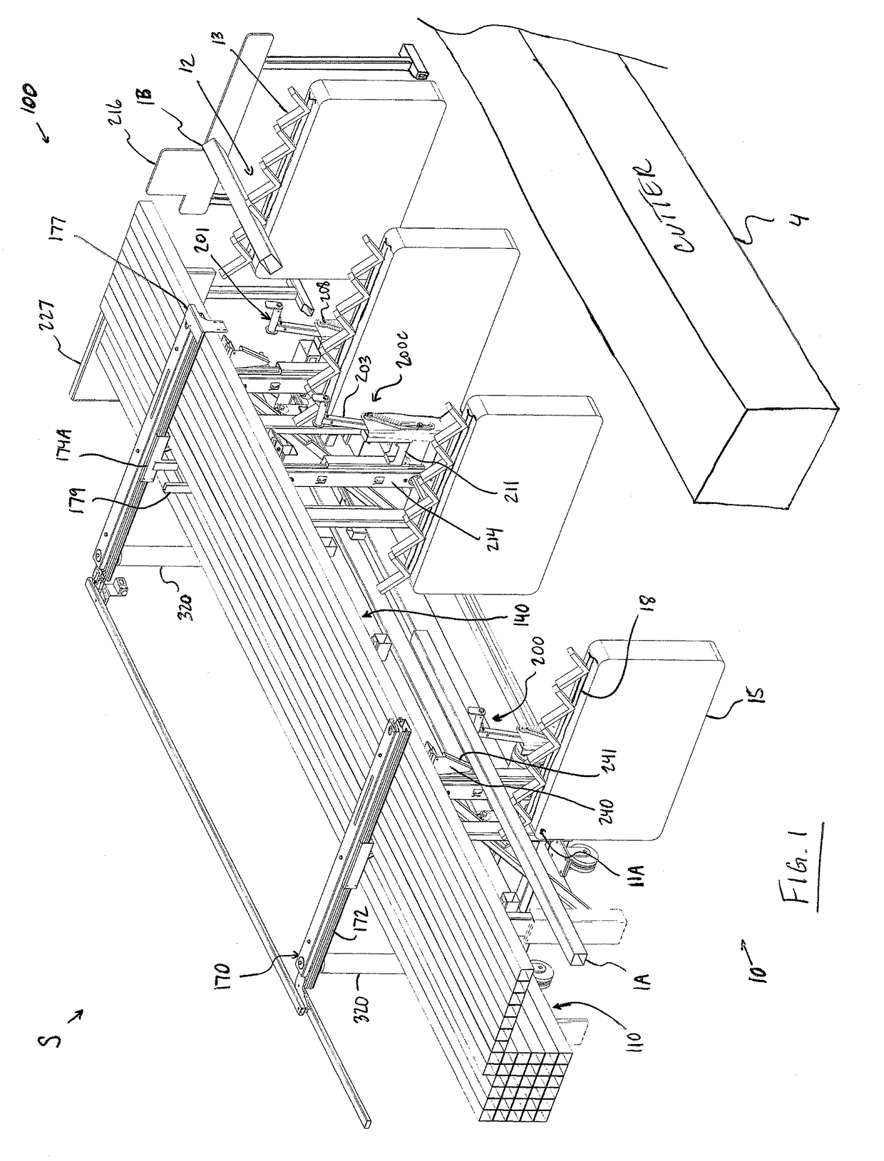
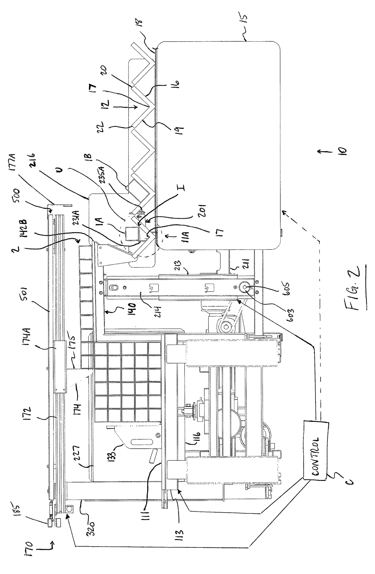
[0069]There is illustrated in the accompanying figures a loading system, which is generally indicated at 100, for loading elongated members 1 onto a conveyor 10 by which the members 1 are then carried to a location downstream of the loading system 100 for processing thereat. (Hereinafter, the loading system may also be referred to as ‘loader’ for short.)

[0070]In the illustrated arrangement the elongated members 1 comprise tubes (having hollow interiors) which are square in cross section, like the tube indicated at 1A. The tubes which can be handled by the loading system 100 are not limited to a square cross-section however and may also, for example, be circular in cross-section or rectangular in cross-section, like the tube indicated at 1B. Furthermore, alternatively to tubes the elongated members may comprise bars (which are solid) which also may have cross-sections of different shapes such as C-shaped as with for example channel iron, L-shaped as with for example angle iron, and I...


PUM


Abstract

A system for loading elongated members, such as metal tubes and bars, onto a conveyor for later processing features an elevator, pusher arms, a support surface provided at a predetermined height, and gripper arms. The elevator acts to lift a topmost layer of the members, which are typically arranged in a stack thereon, to a predetermined height so that the pusher arms may transfer the members forming the topmost layer onto the support surface at this height. The pusher arms push these members across the support surface by engaging the member farthest from the support surface until the respective elongated member passes over a distal side of the support surface and onto the gripper arms arranged at a height of this side. The gripper arms lower that member to an unloading location below the support surface where an empty support cradle of the conveyor is arranged for receiving same.

Description

FIELD OF THE INVENTION[0001]The present invention relates to a system for loading elongated members, for example tubes or bars, onto a conveyor for later processing. The system described in detail in this application is designed particularly but not exclusively for use at an initial stage of an overall material processing system including a laser cutting machine which performs cutting operations on elongated metal members one member at a time.BACKGROUND[0002]In the example of laser cutting machines such as those manufactured by Mazak Corporation, many such cutting machines (also termed ‘cutters’) operate on the members, which are to be cut, one member at a time. The laser cutting machine is itself relatively automated; however, typically a system for feeding members to the cutter machine is substantially manual. That is, the feeding system typically involves loading by hand or by overhead crane each member into a respective movable support carried by a conveyor from which, at a loca...

Claims


Application Information

Patent Timeline
Patent Type & Authority Patents(United States)
IPC IPC(8): E21B19/15B65G17/12B65G25/08B65G59/02B65G47/90
CPCB65G47/904B65G17/12B65G59/026B65G25/08B65G2201/0276B65G2201/0217
Inventor PLETT, DELMER
Owner VIDIR SOLUTIONS INC
Why Eureka
Try Eureka