
Forming process for hot forming a steel sheet of a rotor blade to be produced for a wind energy plant

a technology of forming process and rotor blade, which is applied in the manufacture of final products, soldering apparatus, and auxilary welding devices, etc., can solve the problems of only a severely limited extent of re-use of steel construction experience, and the transfer to the manufacture of rotor blades of wind power installations is basically impossible. , to achieve the effect of more rapid performan

Active Publication Date: 2018-03-27
WOBBEN PROPERTIES GMBH
View PDF32 Cites 1 Cited by
  • Summary
  • Abstract
  • Description
  • Claims
  • Application Information

AI Technical Summary

Benefits of technology

[0014]Preferably the hearth bogie moves on a rail system from the furnace to the pressing apparatus. It is also desirable for the form bogie to travel into the pressing apparatus on a or the rail system. That makes it possible to achieve a simplification in the operating movements, in particular conveying the heated steel sheet from the furnace into the pressing apparatus and on to the counterpart form. Preferably the hearth bogie and the form bogie use the same rail system and in particular the same pair of rails. That makes it possible to achieve an efficient apparatus which also makes the change of the steel sheet from the hearth bogie to the form bogie correspondingly efficient and practical.
[0017]Preferably the forming apparatus in that case is so designed that the hearth bogie can move into the bottom opening or out of same with the carrier structure when the furnace is opened. In particular the bottom opening is in the form of an approximately slot-shaped opening in the furnace bottom and the carrier structure is of a correspondingly slender configuration so that it can move into that slot-shaped opening when the chassis travels under the furnace. After heating of the steel sheet it can thus be easily transported from the furnace to the pressing apparatus. For that purpose it is only necessary for the furnace to be opened and the hearth bogie can travel across to the pressing apparatus.
[0021]Preferably the lifting apparatus has a plurality of lifting arms which are respectively provided with a motion mechanism and which are adapted to laterally engage under the steel sheet. It is proposed in that respect that the lifting arms are so actuated and in particular a corresponding control is provided that they lift the heated steel sheet uniformly, in spite of their own motion mechanisms. As a result the weight is distributed uniformly to the lifting arms and in addition this counteracts the risk that the heated steel sheet could suffer flexural deflection.
[0032]Preferably the preparation arrangement is thus rotated during the welding operation, this being effected in particular at varying speed. The rotor blade segment is of a rather elongated hollow profile in cross-section, with respect to a rotor blade longitudinal axis. By virtue of rotation at a varying speed, it is possible to take account of that fact. In particular the rotor blade is rotated slowly or at times not at all when a correspondingly long profile portion is upward or downward so that the welding robot has sufficient time to weld along a corresponding horizontal weld seam. Accordingly the rotary movement is performed more quickly when only a short portion such as for example a rotor blade leading edge is facing straight down or up in the rotary movement, and is welded.

Problems solved by technology

Steel production is known from many other technological areas such as for example ship building, but transfer to the manufacture of a rotor blade of a wind power installation is basically not possible because of the very special demands of rotor blade manufacture.
In particular it is possible to have recourse to previous experience in steel constructions only to a severely limited extent.

Method used


Image

  • Forming process for hot forming a steel sheet of a rotor blade to be produced for a wind energy plant
  • Forming process for hot forming a steel sheet of a rotor blade to be produced for a wind energy plant
  • Forming process for hot forming a steel sheet of a rotor blade to be produced for a wind energy plant

Examples


Embodiment Construction

[0065]Hereinafter identical references can be used for similar but non-identical components to emphasize the common aspects of the functionality of some such components.

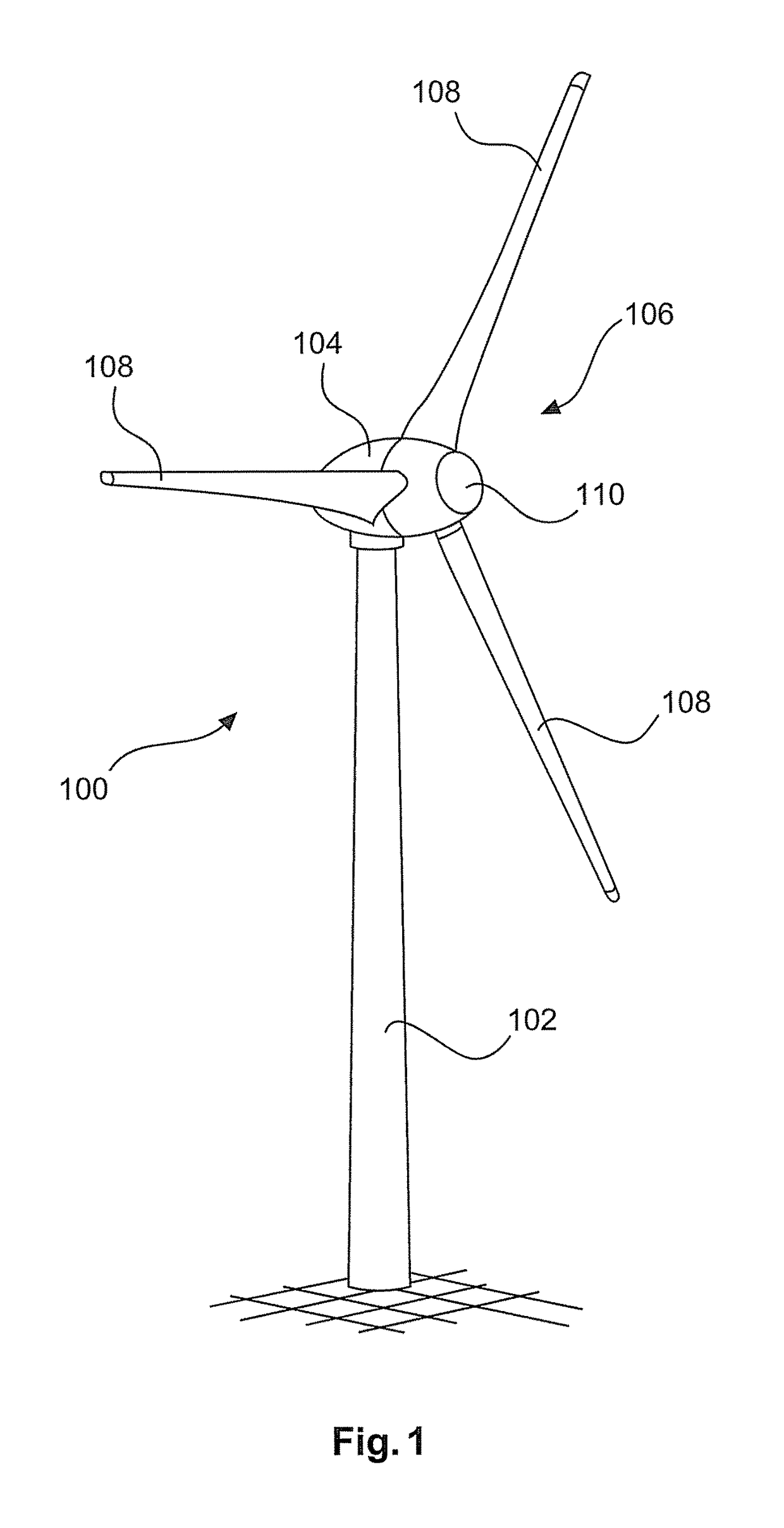
[0066]FIG. 1 shows a wind power installation 100 comprising a pylon 102 and a pod 104. Arranged on the pod 104 is a rotor 106 with three rotor blades 108 and a spinner 110. In operation the rotor 106 is caused to rotate by the wind and thereby drives a generator in the pod 104.

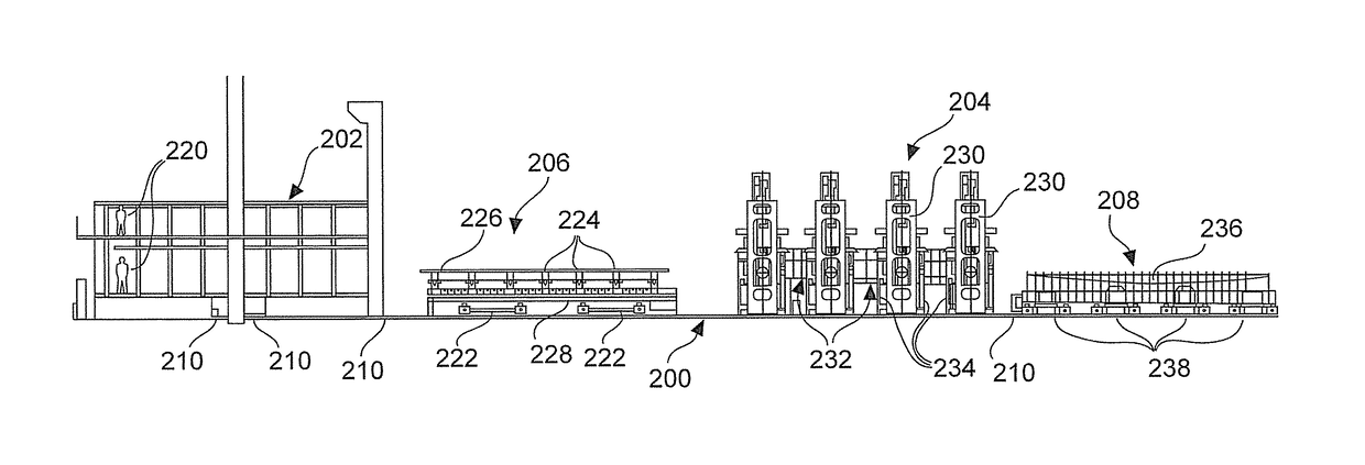
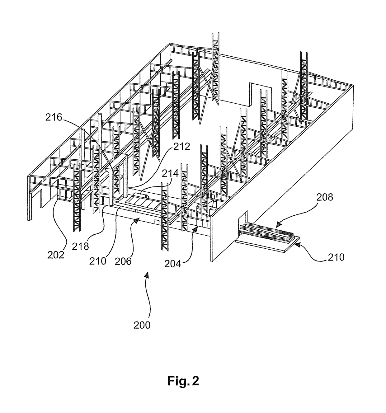
[0067]FIG. 2 shows a perspective view illustrating the overall configuration of a forming station 200. Essential components of that forming station 200 are the furnace 202 which here is in the form of an annealing furnace, the pressing apparatus 204 which can also be referred to as the pressing stand, a hearth bogie 206 which transports steel sheets from the furnace 202 to the pressing stand 204, a form bogie 208 on to which the steel sheet is transferred from the hearth bogie 206 in the pressing apparatus 204 and a rail system 210 connecting t...


PUM

PropertyMeasurementUnit
thicknessaaaaaaaaaa
thicknessaaaaaaaaaa
depthaaaaaaaaaa

Abstract

The present invention concerns a forming process for hot forming of a steel sheet of a rotor blade to be produced of a wind power installation, including the steps heating the steel sheet in a furnace while the steel sheet is lying on a hearth bogie, displacing the heated steel sheet with the hearth bogie from the furnace into a pressing apparatus for the hot forming operation, transloading the heated steel sheet in the pressing apparatus from the hearth bogie on to a form bogie having a counterpart form, and pressing the steel sheet by at least one pressing punch which presses on the steel sheet in such a way that it is formed between the pressing punch and the counterpart form and in particular assumes the shape of the pressing punch and the counterpart form.

Description

BACKGROUND[0001]Technical Field[0002]The invention concerns an apparatus and a process for welding steel sheets for producing a rotor blade of a wind power installation. The invention also concerns a process and an apparatus for the manufacture of a rotor blade of a wind power installation. In addition the invention concerns a wind power installation and a rotor blade of a wind power installation. Furthermore the invention concerns an apparatus and a process for the hot forming of a steel sheet of a rotor blade of a wind power installation. In addition the invention concerns an apparatus and a process for cutting steel sheets to size for a rotor blade of a wind power installation.[0003]Description of the Related Art[0004]Wind power installations are known nowadays in particular in the form of so-called horizontal-axis wind power installations. In that case an aerodynamic rotor having at least one and usually three rotor blades rotates about a substantially horizontal axis. In that c...

Claims


Application Information

Patent Timeline
Patent Type & Authority Patents(United States)
IPC IPC(8): B23P15/04B21D53/78B23K9/18B23K10/00B23K37/047
CPCB23P15/04B21D53/78B23K10/00B23K37/047B23K9/18Y02E10/721Y02E10/72Y02P70/50
Inventor VOIGT, BURKHARDLABS, OLIVERKERSTEN, ROY
Owner WOBBEN PROPERTIES GMBH
Learn More