Multibeam radio frequency photonic beamformer using a multi-signal slow light time delay unit

a radio frequency photonic and time delay technology, applied in the field of beamformers, can solve the problems of bandwidth and scalability, unintentional interference, unintentional fading of wideband signals, etc., and achieve the effects of high throughput, superior performance, and exploiting a relatively untapped spectrum efficiency

Active Publication Date: 2017-12-05
THE TRUSTEES FOR PRINCETON UNIV
View PDF4 Cites 2 Cited by
  • Summary
  • Abstract
  • Description
  • Claims
  • Application Information

AI Technical Summary

Benefits of technology

[0006]Disclosed herein is a photonic multi-beam RF beamformer configured to enable high throughput, scalable space division multiple access (SDMA), and to exploit a relatively untapped spectrum efficiency. The disclosed photonic beamformer is capable of steering multiple beams simultaneously, enabling unique capabilities such as multi-target tracking and dynamic SDMA to take full advantage of the capacity embedded in these spatial channels. The disclosed photonic beamformer has several advantages that result in superior performance compared to the state-of-the-art. For example, it leverages the benefits of optical signal processing, which translates to extremely broad bandwidth operation and immunity to electromagnetic interference. The architecture is highly scalable. By combining the mature wavelength division multiplexing (WDM) technology of the telecom industry with a novel, multi-beam, slow and fast light, true time delay device, the beamformer steers M beams by simply using M distinct wavelengths of light with minimal additional hardware. Compared to multi-beam electrical beamformers, which require M parallel, independent paths and hardware for M beams, the disclosed photonic beamformer exhibits significantly reduced cost, size, weight, and power (C-SWaP). The disclosed photonic beamformer is also semiconductor compatible and naturally lends itself to monolithic integration. The disclosed approach is suitable for manufacture of a multi-beam beamformer photonic integrated circuit (PIC) to realize scalable and robust beamforming.

Problems solved by technology

Electrical RF beamformers are commercially available but traditionally suffer from several issues related to bandwidth and scalability.
The most well-known issue is beam-squint, where different frequency components are steered in slightly different directions because of the use of non-frequency flat RF components and phase shifters, which are inherently frequency sensitive.
Beam-squint can cause unintended interference and unintentional fading of wideband signals; as a result, electrical beamformers are typically narrowband.
However, the cost and size of such systems is often prohibitively large for civilian applications.
Operating N simultaneous beams using electronics is typically performed by using N parallel and independent beamformer structures; in other words, the hardware for multi-beam electrical beamforming is not scalable.
Currently, there are no multi-beam photonic commercial beamformers on the market.

Method used


Image

  • Multibeam radio frequency photonic beamformer using a multi-signal slow light time delay unit
  • Multibeam radio frequency photonic beamformer using a multi-signal slow light time delay unit
  • Multibeam radio frequency photonic beamformer using a multi-signal slow light time delay unit

Examples


Embodiment Construction

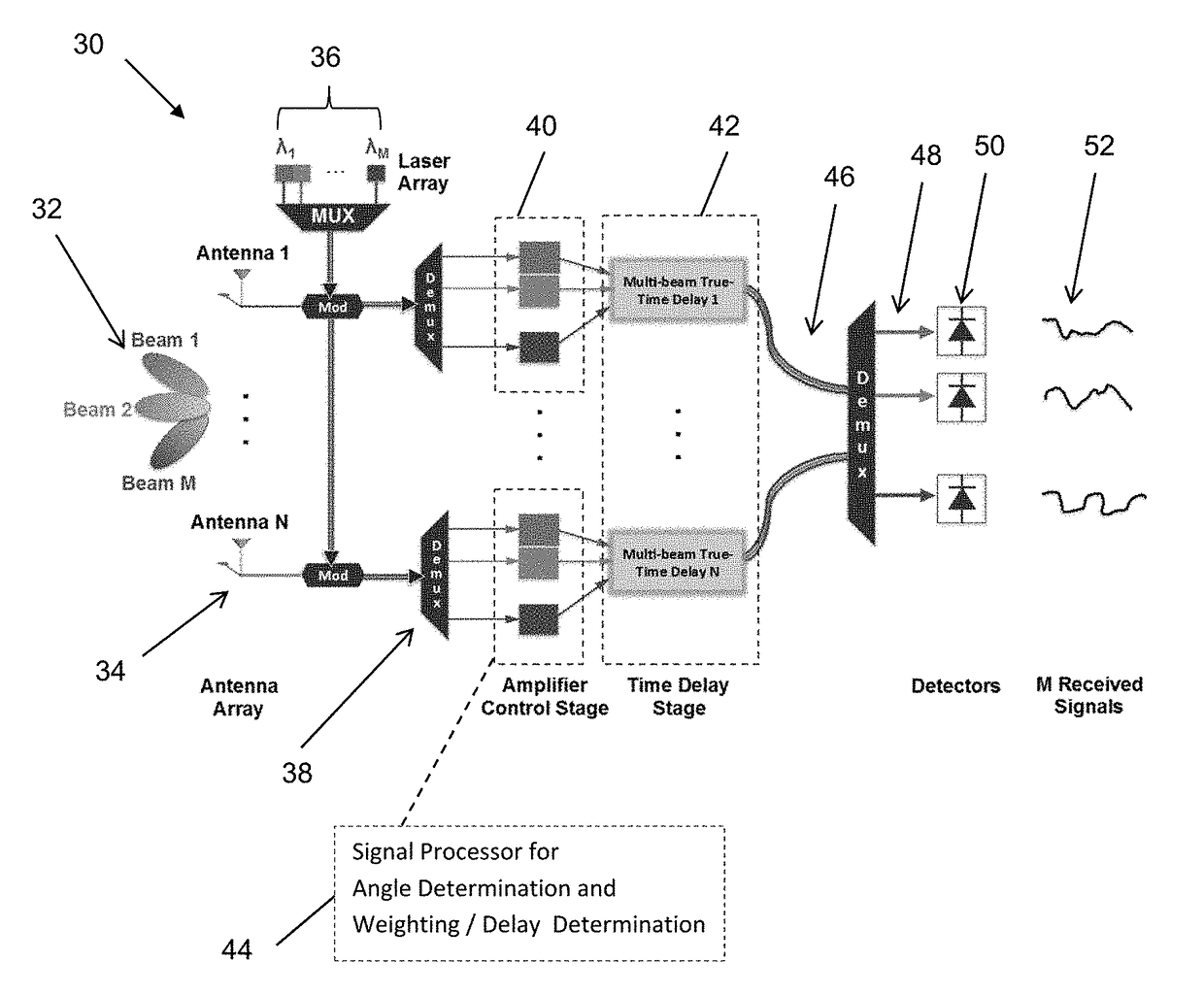
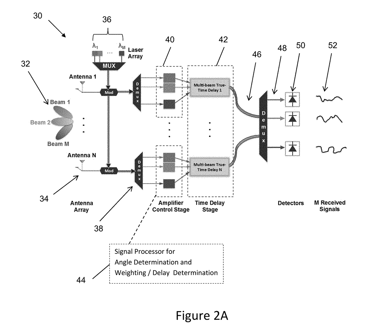
[0026]Disclosed herein is a beamformer architecture that uses a novel multi-beam slow and fast light based TTD, which independently delays multiple distinct wavelength signals in a single, compact device. The multi-beam TTD is an important aspect because it allows the beamformer to enjoy efficient parallel processing using WDM, fast (μs) steering, and semiconductor compatibility to pave the way for a cheap, scalable, and robust PIC beamformer. The full details of the device are set out below. FIG. 2A is a block diagram of a beamformer architecture for a receive beamformer system 30. FIG. 2B is a block diagram of a beamformer architecture for a transmit beamformer system 60. In the case of a receiver, M RF received signals 32 are detected by each of the N elements of the antenna array 34 at slightly different times because of the spacing between antenna elements. The N received RF signals each modulate an optical carrier, which is comprised of M distinct wavelengths 36 shown as λ1-λM...


PUM


Abstract

A photonic beamformer is disclosed andh is configured to transmit or receive a plurality of RF input signals from a plurality of antennas. The beamformer receiver includes a plurality of optical modulators, each optical modulator being configured to modulate each of the RF input signals onto an optical carrier, each carrier having a different wavelength. The beamformer receiver also includes a plurality of optical amplifiers, each optical amplifier being configured to vary the optical power of one optical carrier based on a weighting input and generate a weighted optical carrier. The beamformer receiver also includes a plurality of multi-beam optical true-time delays (TTD), each TTD being configured to receive all of the weighted optical carriers and generate a plurality time delayed optical carriers. The beamformer receiver also includes a plurality of detectors configured to detect each of the plurality time delayed optical carriers and generate an electrical signal that represents each of the plurality of received RF input signals.

Description

CROSS-REFERENCE TO PRIOR FILED APPLICATIONS[0001]This application claims the benefit of U.S. Provisional Application No. 62 / 041,746, filed Aug. 26, 2014, which is incorporated herein in its entirety.TECHNICAL FIELD[0002]The present disclosure generally relates to the field of beamforming spatial filtering and in more particular relates to photonic beamformers.BACKGROUND OF THE INVENTION[0003]Beamforming is the spatial steering of an antenna array pattern for directional transmission or reception. FIG. 1A is a basic pictorial diagram of a beamforming antenna array 12 configured for spatial steering of the antenna array pattern for directional transmission or reception. In this example, the system 10 also includes a plurality of user devices 14 in communication with the antenna array 12 and an interfering user 16. As shown in FIG. 1A, beamforming is used to lock onto and increase the signal-to-noise ratio (SNR) of desired links to the user devices 14, while simultaneously placing inte...

Claims


Application Information

Patent Timeline
Patent Type & Authority Patents(United States)
IPC IPC(8): H04B10/00H04B10/112H04B10/2575H04B7/06
CPCH04B10/25752H04B10/1123H04B7/0617H04Q1/00
Inventor PRUCNAL, PAULCHANG, MATTHEWCHANG, JOHN
Owner THE TRUSTEES FOR PRINCETON UNIV
Why Eureka
Try Eureka