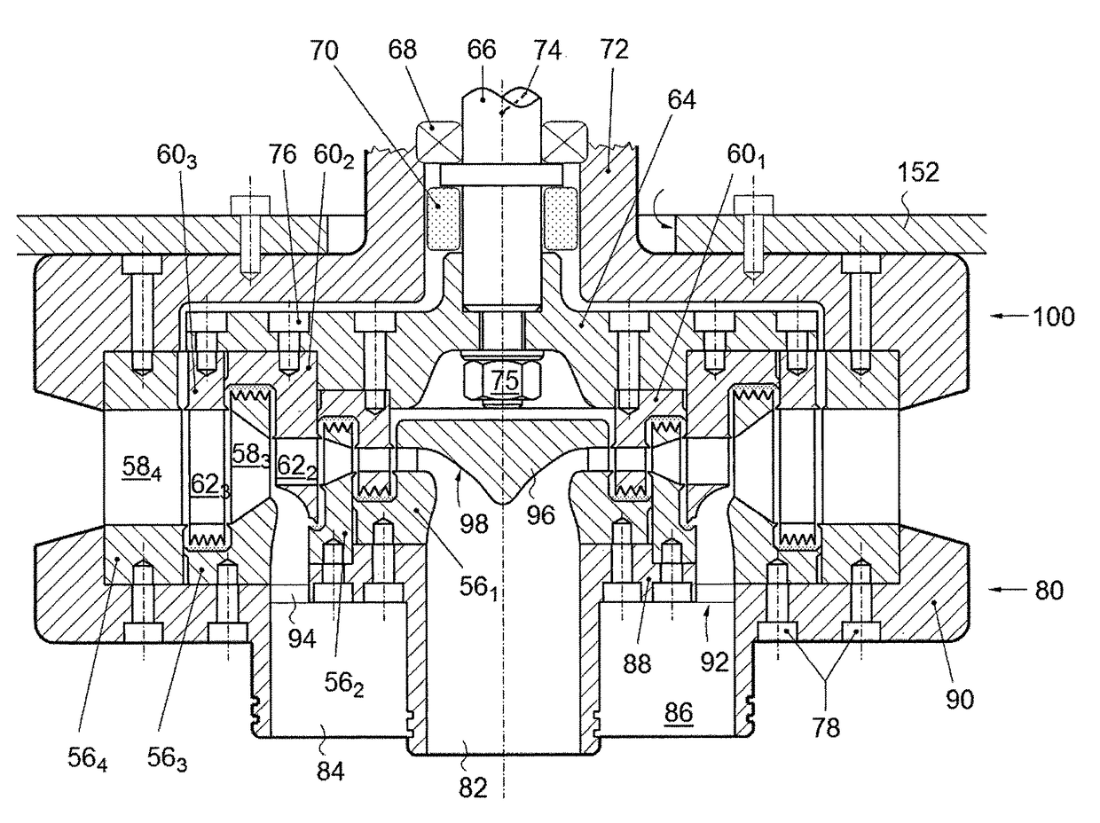
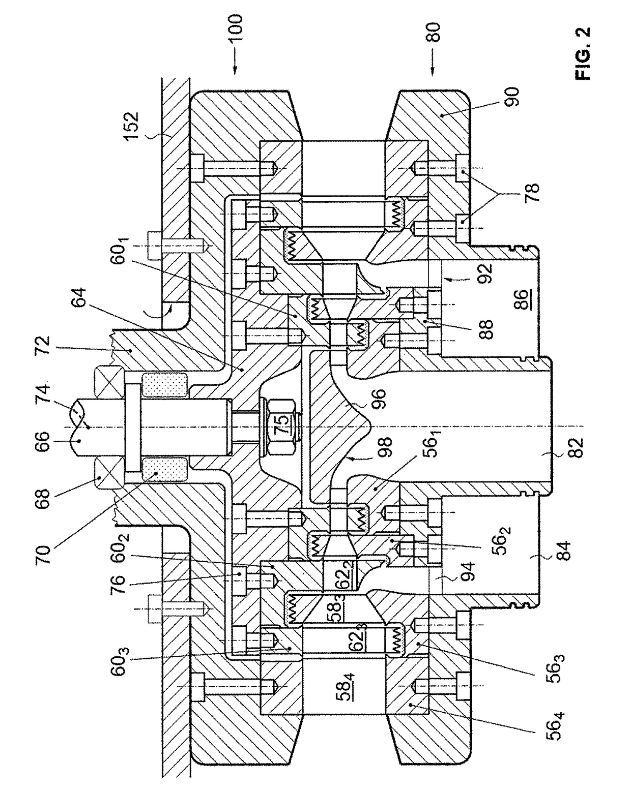
[0012]It will be appreciated that—due to the design of the turbine as a radial-outward-flow type multi-stage turbine—the annular secondary vapour inlet port can be accommodated into the turbine very easily and, basically, without major additional costs. The manufacturing costs for the induction type turbine are not much higher than for a turbine with a single vapour inlet. Indeed, in such a turbine comprising several concentric rings of stator blades, an annular secondary vapour inlet port can be easily accommodated radially between two successive rings of stator blades. The annular configuration of the secondary vapour inlet port warrants low pressure losses at the secondary vapour induction and relatively small perturbations of the radial flow of the main vapour stream. The fact that each turbine stage of such a radial turbine may be easily accommodated to an increased vapour throughput—by simply increasing the height of the stator and rotor blades—makes this type of turbine particularly suitable for vapour induction in an intermediary turbine stage. The fact that the vapour is expanded in successive turbine stages with increasing diameters makes the turbine even more suitable for vapour induction in an intermediary stage. It will further be appreciated that a turbine in accordance with the present invention can be connected with a minimum of pressure losses to a high pressure and a low pressure vapour source.
[0014]The turbine further comprises a rotor, which includes for each turbine stage, a ring of rotor blades radially surrounding a ring of stator blades. In a preferred embodiment, the annular secondary vapour inlet port opens onto an outer annular rim of a rotor ring, in which the rotor blades of a turbine stage are incorporated. This outer annular rim advantageously has a radial width decreasing towards its periphery, so as to form an annular (preferably concave) surface, for annularly deviating the secondary vapour stream, which flows through the annular secondary vapour inlet port, into a ring of stator blades of the next turbine stage, wherein it is merged with the already partially expanded main vapour stream. This embodiment warrants—at very reasonable costs—particularly low pressure losses at the secondary vapour induction and small perturbations of the radial flow of the main vapour stream.
[0015]In this preferred embodiment, the annular (preferably concave) surface, which is formed on the outer annular rim of the rotor ring, advantageously cooperates with an annular (preferably convex) surface, which is formed on a stator ring, in which the stator blades of the next turbine stage are incorporated, so as to define a ring-shaped converging nozzle for injecting the secondary vapour stream, which flows through the annular secondary vapour inlet port, into the ring of stator blades of the next turbine stage. This embodiment even further reduces—at very reasonable costs—pressure losses at the secondary vapour induction and results in still smaller perturbations of the radial flow of the main vapour stream.
[0016]This preferred embodiment of the turbine may further comprise a set of stator rings, with different diameters, with the stator blades incorporated therein, wherein the stator rings are removably fixed (e.g. with screws) on the first turbine housing part. Similarly, the turbine may further comprise a set of rotor rings, with different diameters, with the rotor blades incorporated therein, wherein these rotor rings are removably fixed (e.g. with screws) on a rotor disk. This embodiment allows accommodating the turbine or one or more turbine stages to a different vapour throughput by simply exchanging the stator and rotor rings. The turbine may be easily up-sized or down-sized, and it may be easily fine-tuned to specific working parameters. Hence, an optimal turbine efficiency may nearly always be warranted.
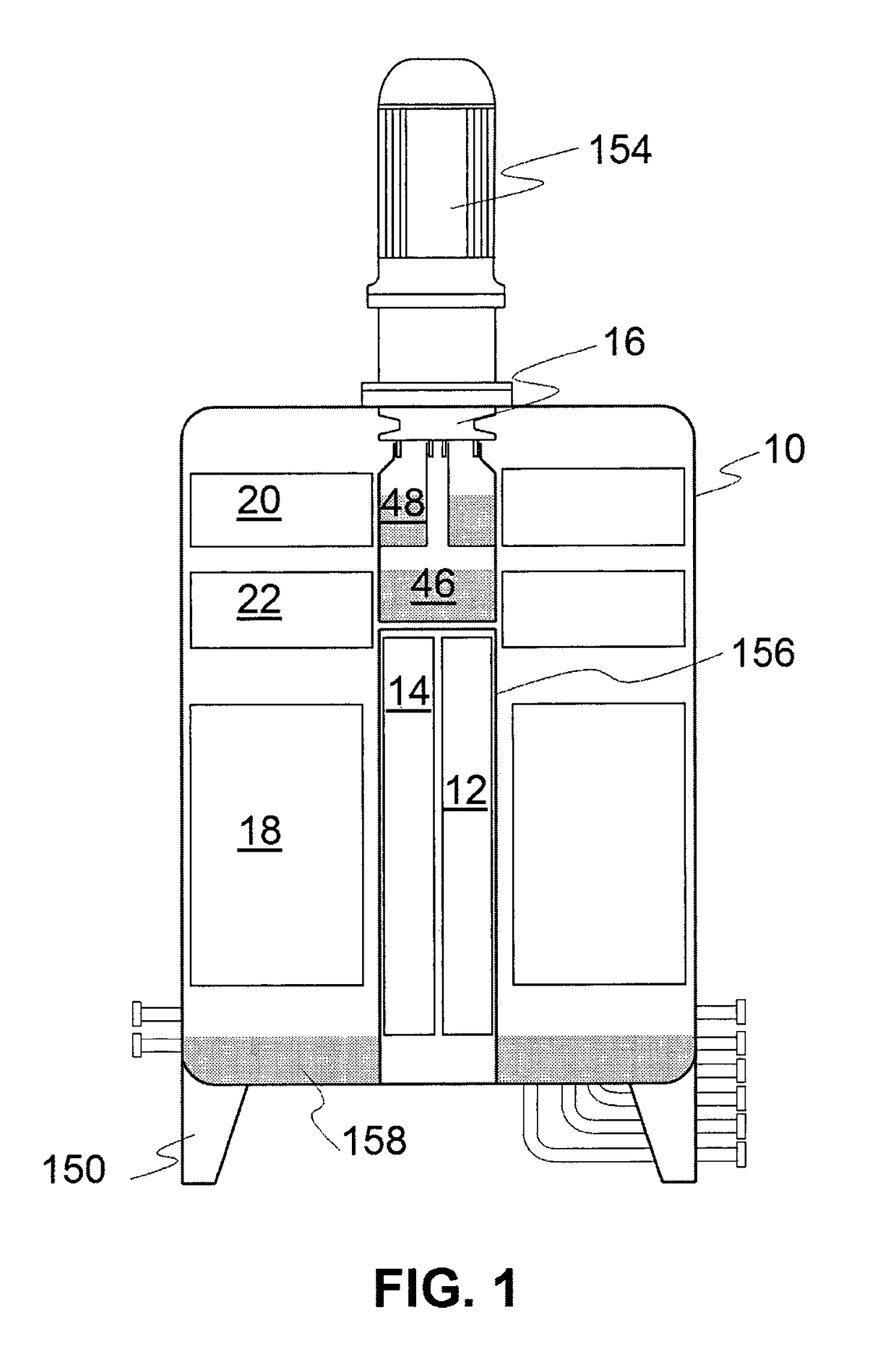
[0021]A preferred embodiment of the turbine may further comprise a first vapour drum that is located in axial extension of the axial main vapour inlet port and directly connected to the latter without any intermediate piping, and a second vapour drum that is located in axial extension of the annular secondary vapour inlet port and directly connected to the latter without any intermediate piping, wherein the second vapour drum is preferably a compartment inside the first vapour drum, or the first vapour drum is, more preferably, a compartment inside the second vapour drum. The axial vapour inlet port advantageously comprises a first tubular vapour inlet connection, which is engaged in a sliding and sealed manner by the first vapour drum, and the annular vapour inlet port advantageously comprises a second tubular vapour inlet connection surrounding the first tubular vapour inlet connection, wherein this second tubular vapour inlet connection is engaged in a sliding and sealed manner by the second vapour drum. Such combined low and high pressure vapour drums, which are connected without any intermediate piping and, preferably, with sliding connections to the turbine vapour inlets, reduce pressure losses at the vapour inlet(s) of the turbine, allow to easily achieve a superheating of the low pressure vapour by the high pressure vapour, thereby increasing efficiency of the Rankine cycle, make the device more compact, facilitate its assembling and reduce its costs.