
Method for manufacturing surgical guide and crown, abutment in mouth for dental implant

a technology of dental implants and surgical guides, which is applied in the field of dental implants, can solve the problems of affecting so as to improve the accuracy of dental implants

Active Publication Date: 2017-12-26
DIO
View PDF12 Cites 18 Cited by
  • Summary
  • Abstract
  • Description
  • Claims
  • Application Information

AI Technical Summary

Benefits of technology

This method enhances the accuracy of dental implant placement and crown design, reducing patient discomfort and procedure costs by providing a reliable and efficient method for determining implant positions and dimensions.

Problems solved by technology

Specifically, in the case of a prosthetic appliance or a denture, other teeth and bones therearound are damaged, as time goes on.
However, the implant may prevent peripheral dental tissues from being damaged, does not have secondary dental caries production factors, and thus may be safely used.
Meanwhile, in a drilling operation for forming the hole at the alveolar bone, it is very difficult for not only an inexperienced dentist but also a skilled dentist to accurately estimate a depth and a direction during the operation.
Further, when a drill is inserted to more than a predetermined depth, there may be a serious problem in that a nerve of the alveolar bone may be damaged.
On the contrary to this, when the drilling operation is terminated before reaching the predetermined depth, an excessive force is required to fix the fixture due to a shallow depth of the formed hole.
Also, there may be other problems in that a screw thread around the hole is damaged, or the fixture is not completely fixed, and thus a reoperation is required later.
However, in a process in which the scanned information is combined, a curvature of a tooth arrangement may be indicated in a distorted state which is different from an actual inside of the mouth, and thus an image correction process is required.
However, in the case of an edentulous patient, since the crown region is lost, it is substantially difficult that the common portion between the three-dimensional image and the three-dimensional external shape image exists.
Therefore, there are some problems in that it is difficult to match the images, and even though the images are matched with each other, inaccurate information is included in a matched image.
Also, when a lower jaw in the mouth is edentulous, the exposed gum region is increased, and movement tissues such as a tongue are distributed, and movability of the tissues is increased, and thus it is difficult for a scanned image to be clearly specified.
Therefore, there is a problem in that it is difficult to obtain a precise external shape through the oral scanning.
Also, even when a reference marker used as a reference point of the image matching is provided at the inside of the mouth, there is another problem in that the reference marker is not substantially fixed due to the movability of the tissues.

Method used


Image

  • Method for manufacturing surgical guide and crown, abutment in mouth for dental implant
  • Method for manufacturing surgical guide and crown, abutment in mouth for dental implant
  • Method for manufacturing surgical guide and crown, abutment in mouth for dental implant

Examples


first embodiment

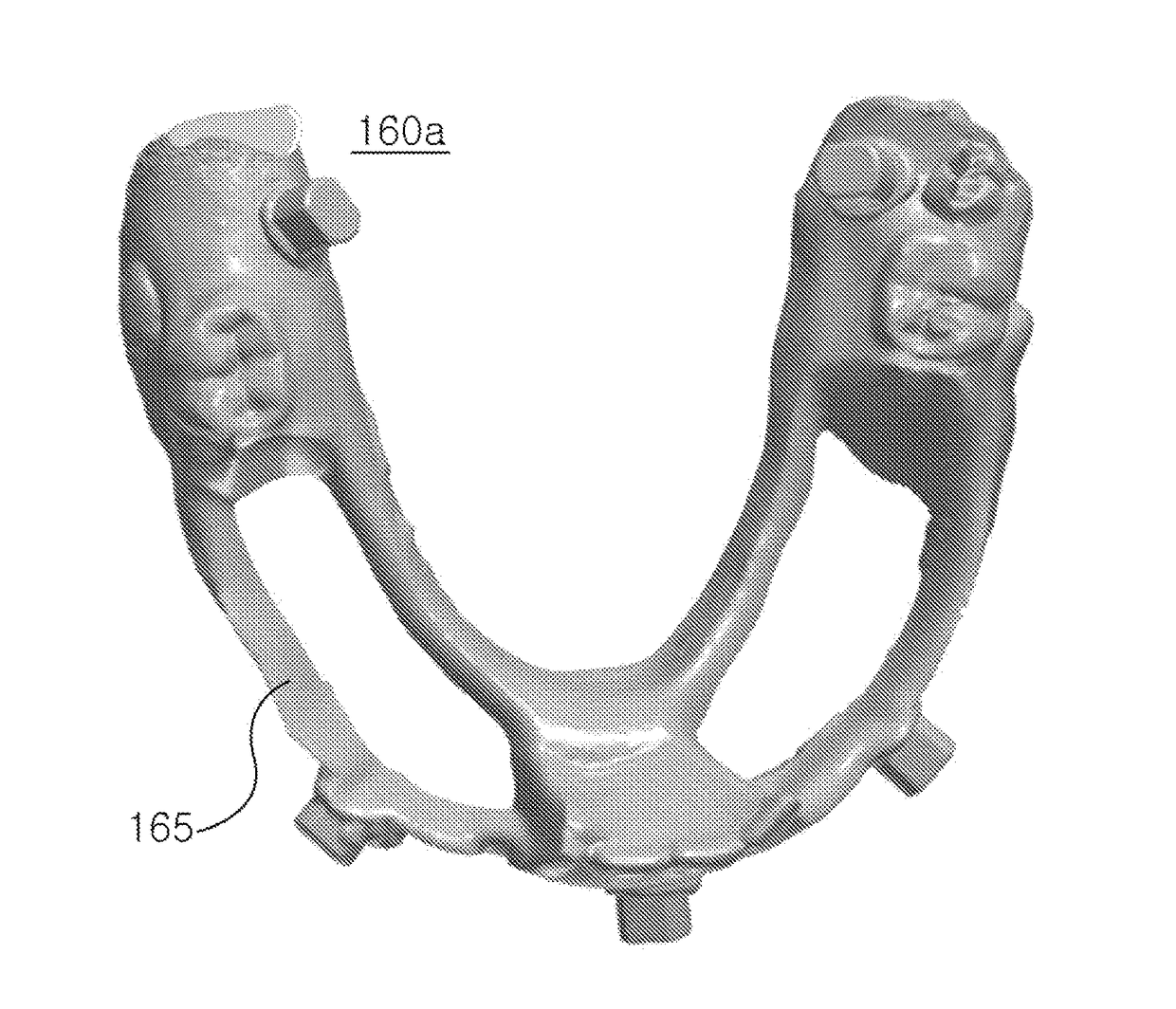
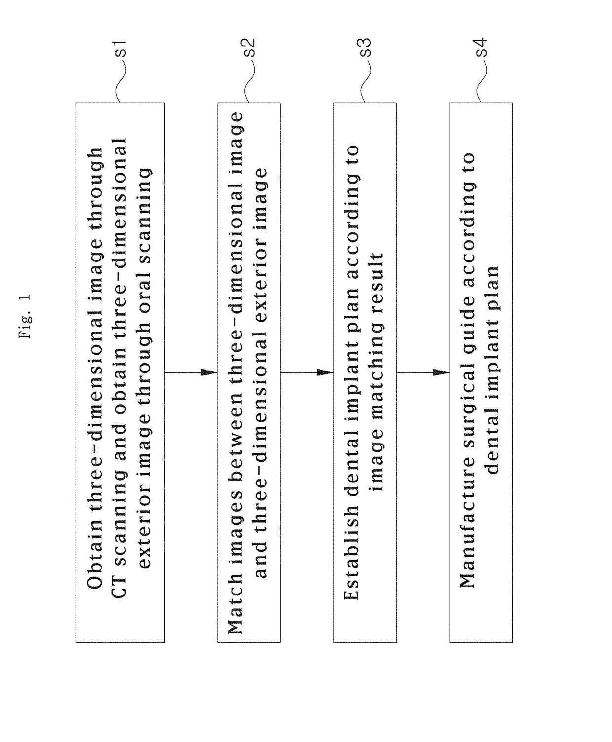
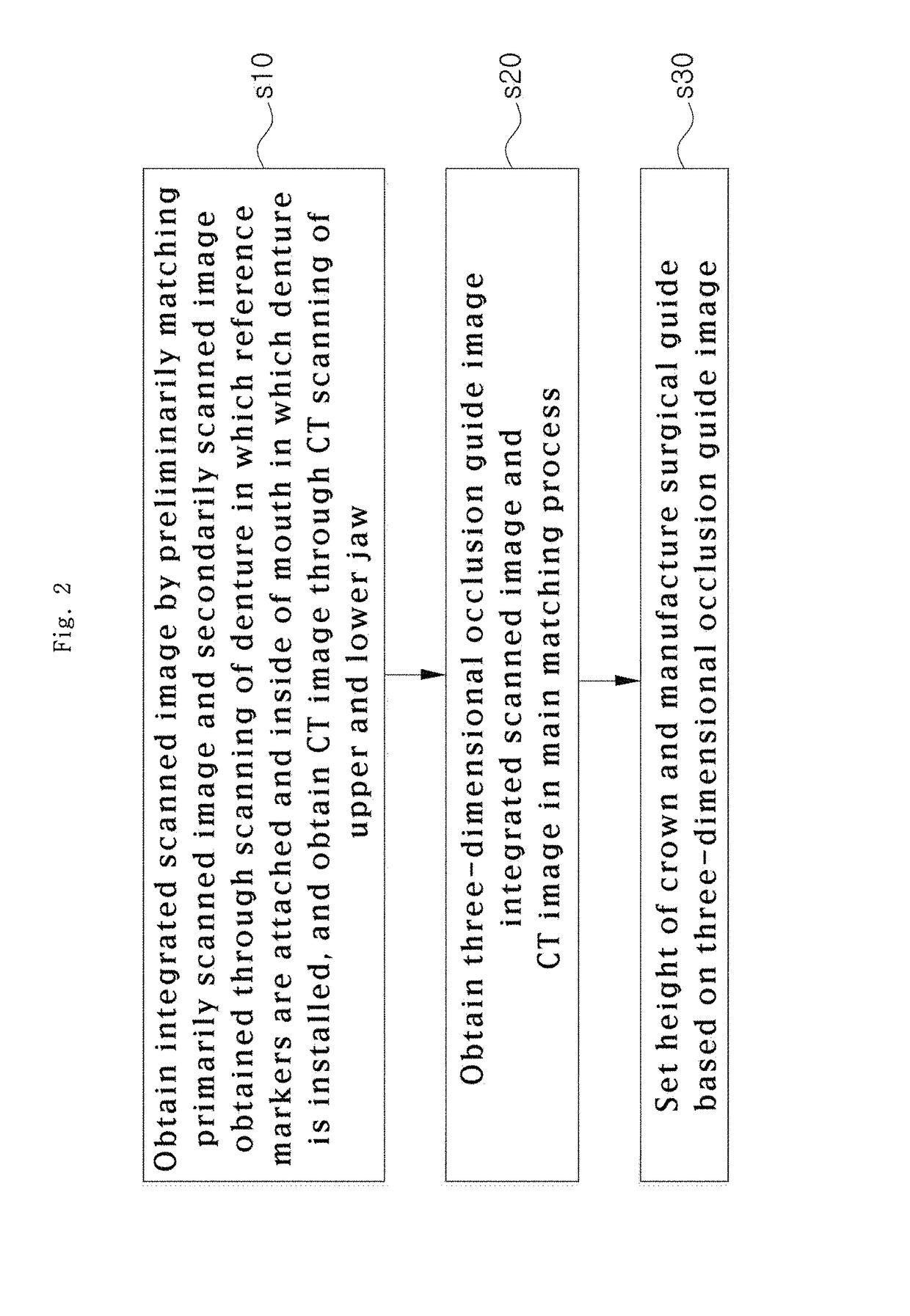
[0049]Specifically, as illustrated in FIGS. 2 to 8, the method for manufacturing the surgical guide, and the crown and the abutment in the mouth for the dental implant according to the present invention proceeds as follows. At this time, the method for manufacturing the surgical guide, and the crown and the abutment in the mouth for the dental implant may be applied to a dental implant of a patient whose at least one of upper jaw and lower jaw is edentulous.

[0050]Here, it may be understood that an implantation material in the dental implant includes a fixture which replaces a tooth root, a crown which replaces a crown, and an abutment which connects between the fixture and the crown. Also, manufacturing of the implantation material includes manufacturing of the crown corresponding to a tooth arrangement and a vertical dimension of a patient, and may also include selecting of the fixture and the abutment standardized corresponding to patient's bone tissues. Of course, if necessary, t...

second embodiment

[0200]An occlusal base having a predetermined thickness is stacked on an outside of the splint 80. Here, the occlusal base may be stacked to have a thickness corresponding to a space between the opposing tooth and an upper surface of the splint 80, while the splint is installed at the tooth implanting portion and the upper and lower jaws are occluded. At this time, a basic structure of the occlusal base and a method for setting an occlusal height are the same as those of the second embodiment, and thus detailed description thereof will be omitted.

[0201]Meanwhile, while the splint 80 in which the occlusal height is set by adjusting the thickness of the occlusal base is installed at the patient's tooth implanting portion, the CT scanning is performed, and thus the CT image 314 considering the vertical dimension is obtained (s330).

[0202]Here, the CT image 314 includes the image of the reference markers 40 inserted into the marker grooves 81 of the splint. And since a shape of the oppos...


PUM


Abstract

Provided is a method for manufacturing a surgical guide, and a crown and an abutment in a mouth for a dental implant, including an operation of obtaining a primarily scanned image through scanning of inner and outer surfaces of a denture which has a first image matching groove matched with a patient's tooth implanting portion and in which a plurality of reference markers are attached to an outside, obtaining a secondarily scanned image through oral scanning of upper and lower jaws while the denture is installed, preliminarily matching the secondarily scanned image with the primarily scanned image, obtaining an integrated scanned image considering a vertical dimension by reversing the first image matching groove so that an image of the first image matching groove is dimensionalized from the primarily scanned image, and obtaining a CT image through CT scanning of the upper and lower jaws.

Description

CROSS-REFERENCE TO RELATED APPLICATION[0001]This application claims the benefit of Korean Application No. 10-2014-174007 which was filed on Dec. 5, 2014, and Korean Application No. 10-2015-29756 which was filed on Mar. 3, 2015, and Korean Application No. 10-2015-32445 which was filed on Mar. 9, 2015, and Korean Application No. 10-2015-48380 which was filed on Apr. 6, 2015, which were hereby incorporated by references as if fully set forth herein.BACKGROUND[0002]1. Field of the Invention[0003]The present invention relates to a dental implant, and more particularly, to a method for manufacturing a surgical guide, and a crown and an abutment in a mouth for a dental implant, which precisely obtains an image of an inside of a patient's mouth, and thus enhances accuracy of the dental implant.[0004]2. Discussion of Related Art[0005]Generally, an implant is a substitute for a part of a human organism, when the part of the human organism is lost. However, in the field of dentistry, an implan...

Claims


Application Information

Patent Timeline
Patent Type & Authority Patents(United States)
IPC IPC(8): A61C13/00A61C8/00A61C13/271A61C9/00A61C19/05A61C5/70A61C5/77A61B6/14A61B6/03A61C1/08A61B90/00A61B6/51
CPCA61C13/0004A61B6/032A61B6/14A61C1/084A61C5/70A61C5/77A61C8/0048A61C9/004A61C9/0006A61C13/26A61C19/05A61C8/005A61C2201/005A61B2090/3966A61B6/51
Inventor KIM, JIN CHULKIM, JIN BAEKCHOI, BYUNG HOJUNG, SEUNG MI
Owner DIO
Learn More