Cord guide device and sewing machine provided with same
a technology of guide device and guide cord, which is applied in the direction of embroidering machine, automatic machine, textiles and paper, etc., can solve the problems of disadvantageous complexity and cost of sewing machine, and achieve the effect of reliably guiding the cord, reducing the rise of cloth, and simple and compact structur
- Summary
- Abstract
- Description
- Claims
- Application Information
AI Technical Summary
Benefits of technology
Problems solved by technology
Method used
Image
Examples
first exemplary embodiment
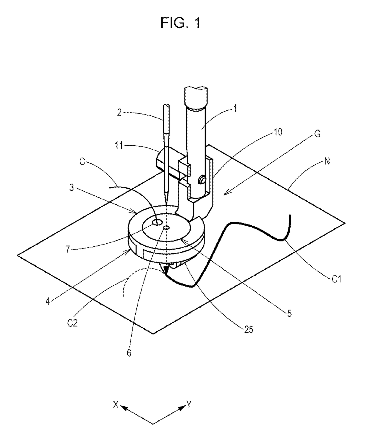
[0030]A guide attachment rod 1 illustrated in FIG. 1 is fixed to a sewing machine body (not shown) and is provided immediately behind a sewing needle 2 so as to hang therefrom when viewed from a sewer positioned on a front side of the sewing machine.
[0031]A cord guide device G is attached to a lower end of the guide attachment rod 1 through a holder arm 10 with a bolt 11.
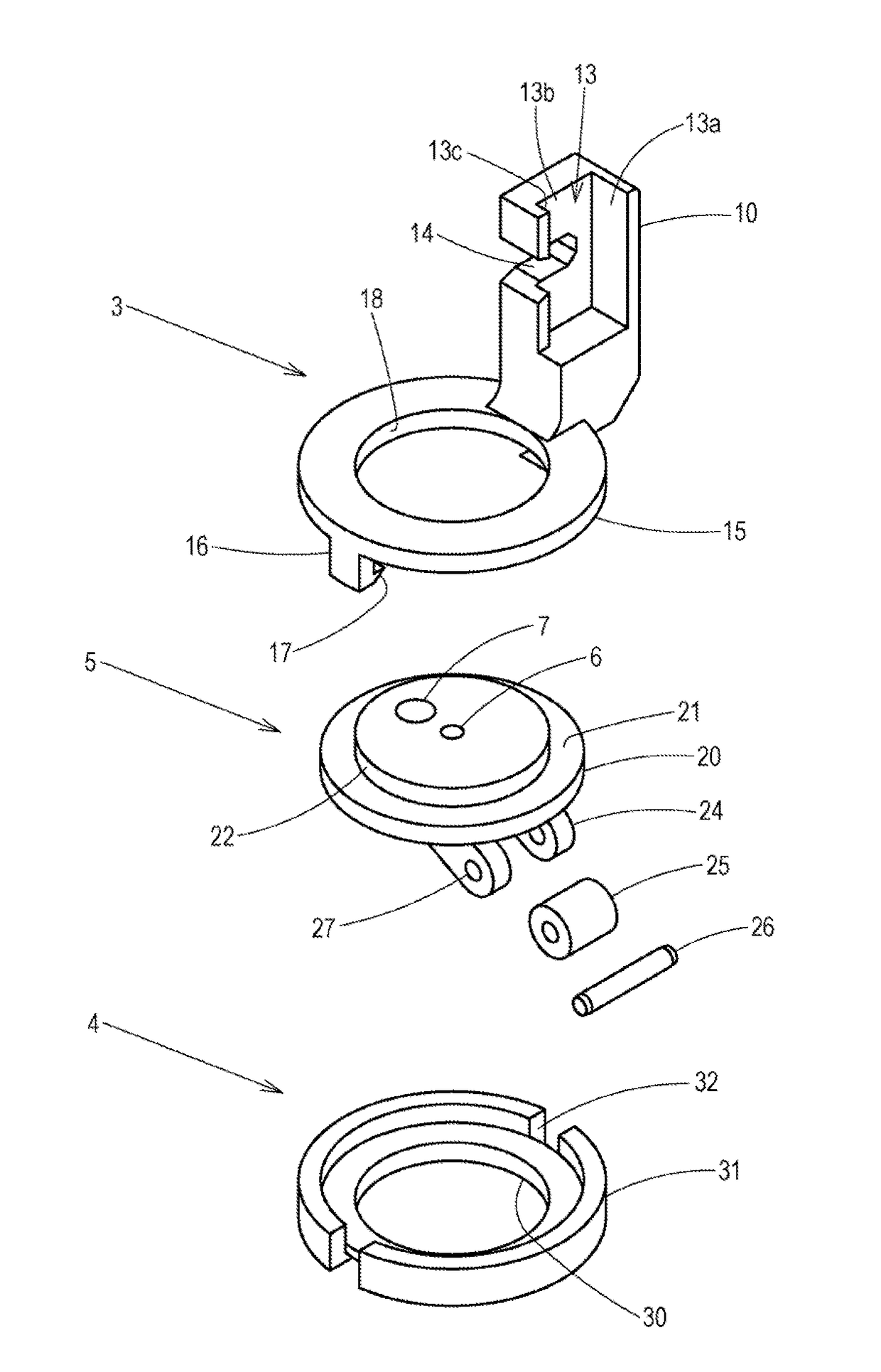
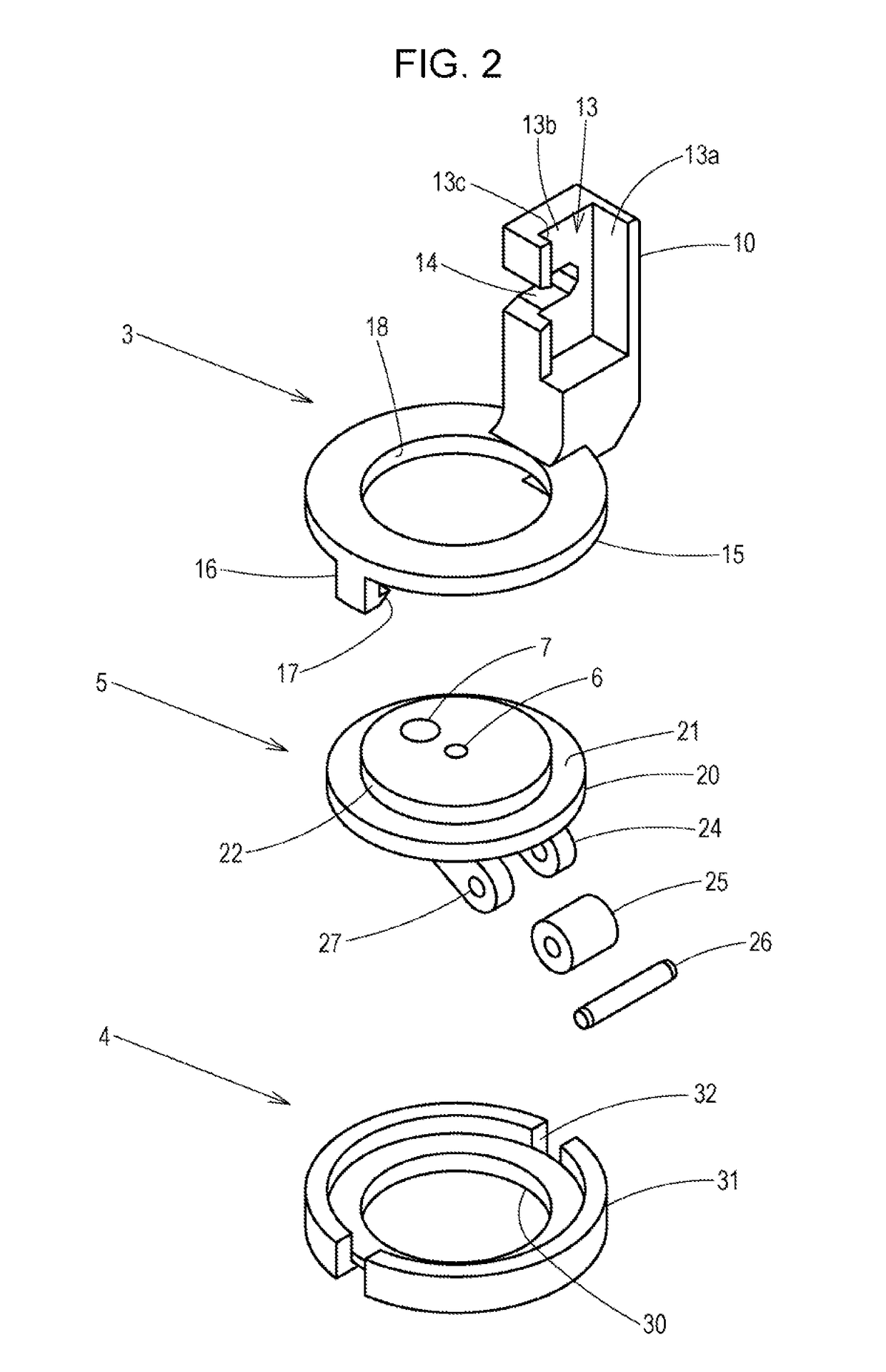
[0032]The cord guide device G includes a disc-shaped cord guide 5 that includes a needle hole 6 through which the sewing needle 2 is passed and a guide hole 7 through which a piece of cord C is passed, a guide support board 4 that supports an underside of the cord guide 5, and a pressing holder 3 that restricts an upper surface of the cord guide 5 and that is mounted on the guide attachment rod 1 with the holder arm 10.
[0033]A roller 25 described later is attached to a lower portion of the cord guide 5 so as to be in contact with a piece of cloth N.
[0034]Reference numeral N in FIG. 1 is a piece of cloth onto which a...
second exemplary embodiment
[0065]A second exemplary embodiment in which the cord guide is made rotatable by an operation lever and in which the connection mechanism of the pressing holder and the guide support board is changed will be described next.
[0066]Hereinafter, components that are the same as the first exemplary embodiment will be designated with the same reference numerals and points that are different will be described mainly.
[0067]As illustrated in FIGS. 7A to 8C, the cord guide 5 is equipped with an operation reception portion 43 that includes an insertion hole 44 into which an insertion piece 41 of an operation lever 40 can be fitted.
[0068]The operation reception portion 43 is provided on the underside of the base 20 so as to protrude therefrom and is provided on the outside of the guide arms 24 and inside an inner peripheral edge of the bottom plate 30 of the guide support board 4.
[0069]In the present exemplary embodiment, the insertion piece 41 is a flat tabular member and the insertion hole 44 ...
third exemplary embodiment
[0087]A third exemplary embodiment provided with, as a rotation mechanism, a drive mechanism that rotates the cord guide according to a moving direction of the cloth detected by an angle sensor will be described next.
[0088]Hereinafter, components that are the same as the first exemplary embodiment will be designated with the same reference numerals and points that are different will be described mainly.
[0089]As illustrated in FIGS. 9A and 9B, a driven gear 61 is provided on the outer peripheral edge of the base 20 of the cord guide 5. A drive mechanism 60 including a drive gear 62 that meshes with the driven gear 61 is accommodated inside a base 66 provided in the base portion of the holder arm 10 of the pressing holder 3.
[0090]A pulse motor 63 that rotates a shaft 64 on the basis of information from an angle sensor (not shown) is attached to the shaft 64 of the drive gear 62. The pulse motor 63 is mounted in the base 66 so as not to rotate.
[0091]In the present exemplary embodiment,...
PUM
 Abstract
Description
Claims
Application Information
 - R&D
- Intellectual Property
- Life Sciences
- Materials
- Tech Scout
- Unparalleled Data Quality
- Higher Quality Content
- 60% Fewer Hallucinations
Browse by: Latest US Patents, China's latest patents, Technical Efficacy Thesaurus, Application Domain, Technology Topic, Popular Technical Reports.
© 2025 PatSnap. All rights reserved.Legal|Privacy policy|Modern Slavery Act Transparency Statement|Sitemap|About US| Contact US: help@patsnap.com


