Piston rod for a piston compressor, and the piston compressor

a piston compressor and piston rod technology, which is applied to the positive displacement pump components, liquid fuel engine components, and positive displacement liquid engines, etc., can solve the problems of lubricant getting dissolved in the gas or liquid being sealed, oil-lubricated compressors are not suitable for sensitive media such as are used, and the contact site of sliding parts is affected by tribological changes, so as to achieve reliable cooling of the piston rod seal, good heat flow, and easy production

Inactive Publication Date: 2018-01-16
NEUMAN & ESSER GMBH & CO KG
View PDF19 Cites 2 Cited by
  • Summary
  • Abstract
  • Description
  • Claims
  • Application Information

AI Technical Summary

Benefits of technology

[0020]Thus, the problem of the invention is to provide a piston rod for piston compressors that enables a good heat flow from the seal packing region and thus a reliable cooling of the piston rod seal and that can be produced more easily than the prior art, being more robust and less maintenance-demanding.

Problems solved by technology

However, the oil lubrication comes with the risk of lubricant getting dissolved in the gases or liquids being sealed.
Consequently, oil-lubricated compressors are unsuitable for sensitive media such as are used, for example, in the food industry or in the medical field.
However, without the oil lubrication being present there are great changes in the tribological properties at the contact sites of the sliding parts.
However, extensive tribological studies have shown that this increased temperature in turn has a negative impact on the rates of wear of the sliding parts.
In the worst case, this can result in premature failure of the compressor.
Thus, an effective cooling of the sliding parts constitutes a major problem with dry lubrication.
However, the cooling is not very effective, since a process gas present between the contact surface and the chambers prevents a good heat flow.
This low thermal conductivity necessarily results in a large temperature gradient from the seal packing region (high temperature) to the region away from the seal packing (low temperature).
But this device has the drawback that ports for the flowing coolant need to be provided at the piston rod.
Both the ports and the pump increase the cost and maintenance expense of such cooled piston rods.
Moreover, an unnoticed failure of the circulating pump results in an immediate rise in temperature of the piston rod and thus concomitant damage to it.
Therefore, the functionality of the circulating pump must be constantly monitored, which likewise entails increased cost and time expense.

Method used


Image

  • Piston rod for a piston compressor, and the piston compressor
  • Piston rod for a piston compressor, and the piston compressor
  • Piston rod for a piston compressor, and the piston compressor

Examples


Embodiment Construction

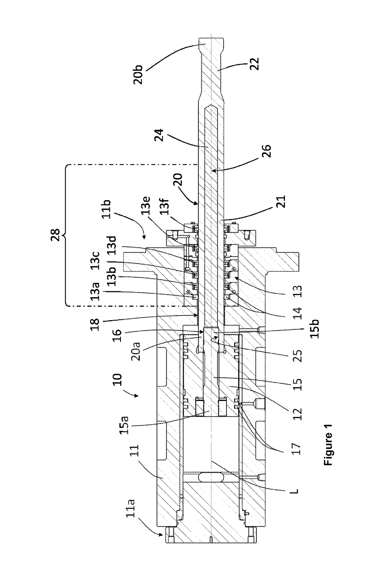
[0061]FIG. 1 shows a cross sectional representation of a piston compressor 10. The piston compressor 10 has a cylinder 11, which is closed at a first end 11a and at the second end 11b has an opening 18 for the passage of a piston rod 20.

[0062]Inside the cylinder 11 is arranged a piston 12 able to move in the direction of the longitudinal axis L of the compressor 10. The piston 12 has piston seals 17 and a connecting part 15, which joins the piston 12 to the piston rod 20. The connecting part 15 extends through the piston 12 and is connected by a first end 15a to the piston 12. By a second end 15b the connecting part 15 is fastened to the piston rod 20.

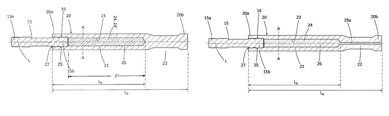
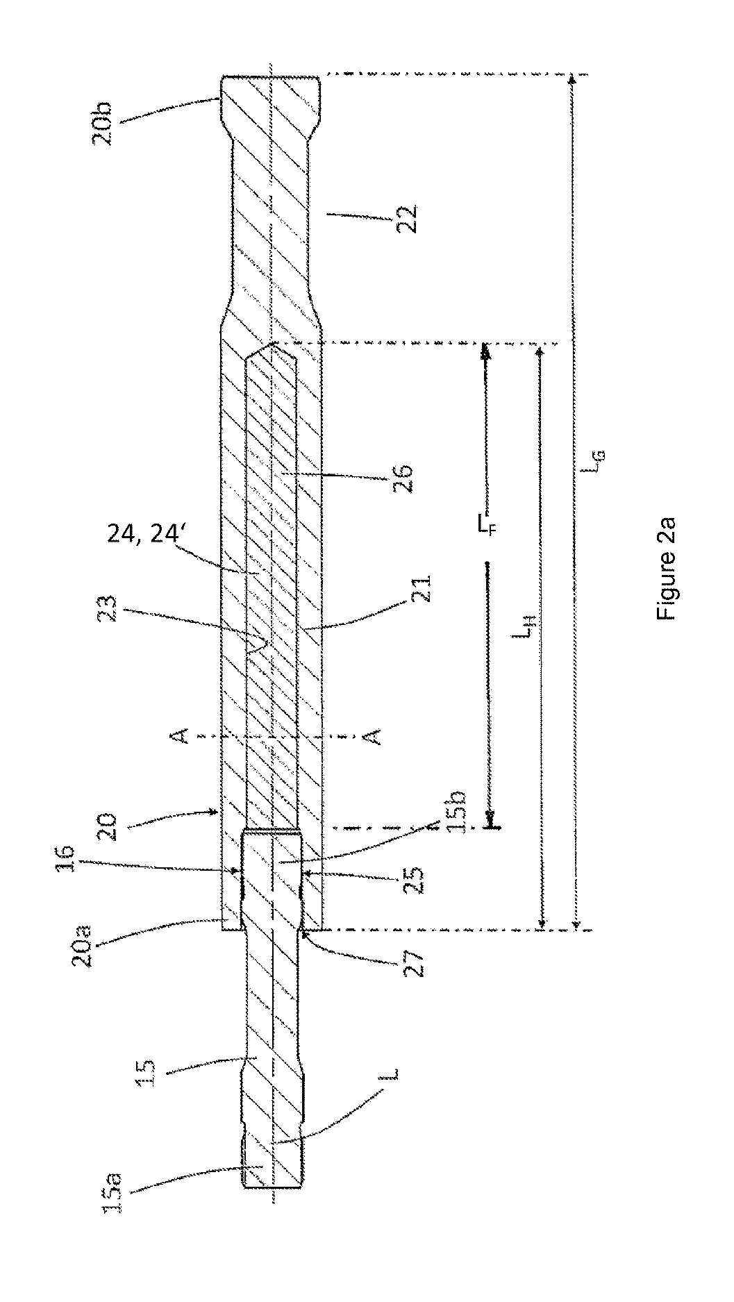
[0063]The piston rod 20 has an end 20a facing the piston and an end 20b away from the piston, while the end 20a facing the piston is joined to the connecting part 15. The piston rod 20 has a base body 21 made of a steel material with a connection segment 22, on which a cross head (not shown) can be mounted. The base body 21 is partly f...


PUM


Abstract

A piston rod for piston compressors, wherein the piston rod has a base body with one end facing the piston, one end away from the piston, and at least one cavity. The cavity is filled with a solid, whose specific thermal conductivity is greater than that of the base body.Furthermore, the invention concerns a piston compressor with a piston and a nonlubricated piston rod seal, wherein the piston is connected to the described piston rod.

Description

FIELD OF THE INVENTION[0001]The present invention concerns a piston rod for piston compressors, having a base body with one end facing the piston, one end away from the piston, and at least one cavity. Moreover, the invention concerns a piston compressor with such a piston rod.BACKGROUND OF THE INVENTION[0002]Compressors and especially piston compressors are standard for the compressing of liquids or gases. In order to minimize the friction forces occurring between the moving parts of the compressors, compressors with oil lubrication are preferred. This oil lubrication has the task of providing a preferably hydrodynamic tribological contact between the sliding parts at the piston and guide rings and at the seals of the piston rod. Thanks to this tribological contact, very low rates of wear can be achieved for these sealing elements. Thus, standard lifetimes for lubricated machines of over 25000 hours with no significant wear can be achieved.[0003]However, the oil lubrication comes w...

Claims


Application Information

Patent Timeline
Patent Type & Authority Patents(United States)
IPC IPC(8): F04B39/00F04B53/08F04B39/06F04B53/14
CPCF04B53/144F04B53/08F04B39/06F04B39/0022
Inventor HOFF, KLAUS HUBERT
Owner NEUMAN & ESSER GMBH & CO KG
Why Eureka
Try Eureka