Transmitter pen positioning system

a positioning system and transmitter pen technology, applied in the field of positioning systems, can solve the problems of generating unwanted audible noise to users, requiring more power, and limited real-time update frequency of the transmitter's location, so as to simplify the system and reduce costs , the effect of reducing consumption

Inactive Publication Date: 2018-01-16
HOU ALFRED SAMSON
View PDF10 Cites 0 Cited by
  • Summary
  • Abstract
  • Description
  • Claims
  • Application Information

AI Technical Summary

Benefits of technology

[0007]Accordingly, the transmitter pen positioning system is used to simplify system complexity, reduce costs, and lower consumption, implement the real-time position calculation, and further overcome the above-mentioned problems.

Problems solved by technology

In these conventional schemes, the real-time update frequency of the transmitter's location is limited by the maximum rotation speed of the motors used.
Due to the use of mechanical moving parts such as DC motors, product reliability and lifetimes may be more limited, these conventional systems also require more power, and can generate unwanted audible noise to the user.
Highly accurate position detection depends on knowing the exact angle of the motor shaft, which can require complicated calibration and assembly or the use of expensive stepper motors.
These systems require laser or RF pulses with ultrafast rise time as well as high-speed receivers, all of which add to the cost and complexity of the system.
Since sound travels at much slower speeds than light, there are fewer burdens on the system electronics to measure precise signal arrival times. However, ultrasound transmitters and receivers tend to be narrow-band devices and thus hard to pinpoint arrival times without sophisticated algorithms.
Also, ultrasound transducers tend to be specialized components made of piezo-electric thin films and / or exotic materials, which are produced in limited quantities and thus can be costly.

Method used


Image

  • Transmitter pen positioning system
  • Transmitter pen positioning system
  • Transmitter pen positioning system

Examples


Embodiment Construction

[0022]Reference will now be made to the drawing figures to describe the present disclosure in detail.

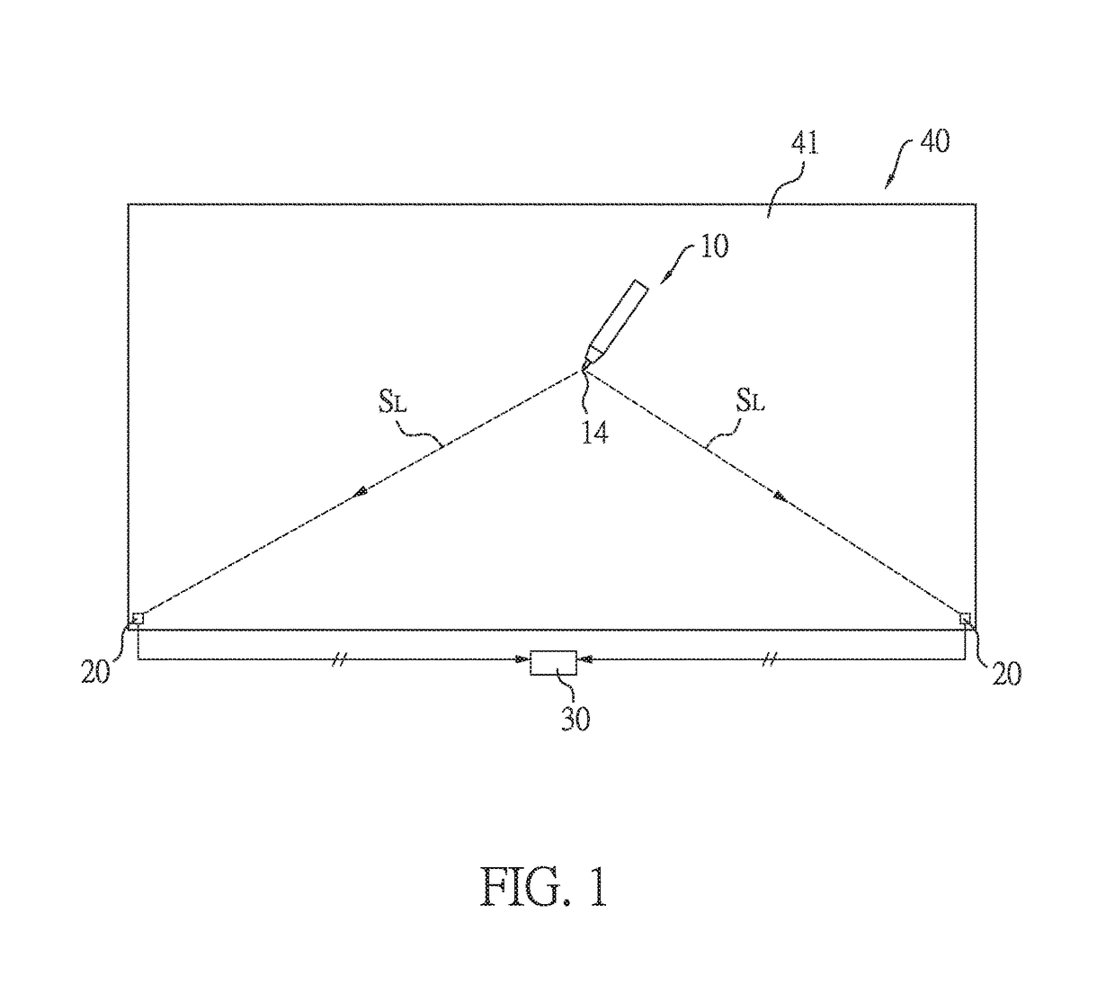
[0023]As shown in FIG. 1, in this embodiment, the transmitter pen positioning system is, but not limited to, applied to a writing board 40 with a writing surface 41, such as a whiteboard. The transmitter pen positioning system includes a transmitter pen 10, at least two photo-receiving modules 20, and a signal processing unit 30.

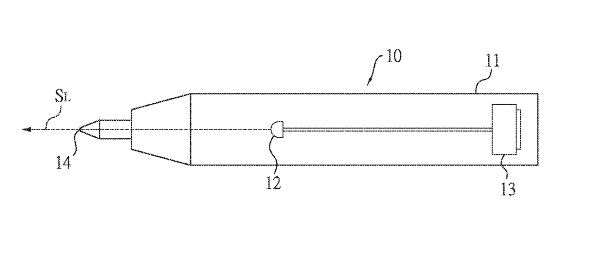
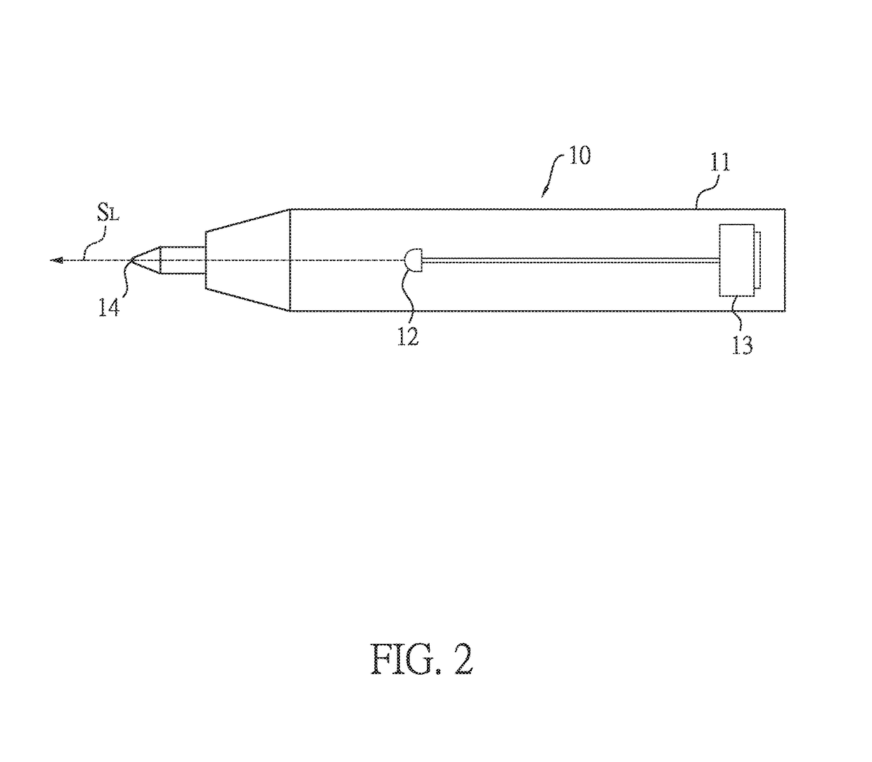
[0024]As shown in FIG. 2, the transmitter pen 10 has a pen body 11, a light emitting element 12, a power supplying element 13, and a pointing tip 14. The light emitting element 12 and the power supplying element 13 are disposed in the pen body 11. Also, the light emitting element 12 can be, but not limited to, a light-emitting diode (LED) or a laser diode. The power supplying element 13 can be, but not limited to, a battery, such as a coin battery also called a button cell battery. Also, the power supplying element 13 is used to supply required power to the t...


PUM


Abstract

A transmitter pen positioning system includes a transmitter pen, at least two photo-receiving modules, and a signal processing unit. The transmitter pen generates a light beam signal. Each photo-receiving module has an optical lens and a photo-receiving sensor. The photo-receiving sensor receives the light beam signal passing through the optical lens via a first photo-receiving surface and a second photo-receiving surface and correspondingly converts the light beam signal into a first photocurrent signal and a second photocurrent signal. The signal processing unit receives the first and the second photocurrent signals, and correspondingly calculates an incident angle of the light beam signal according to a difference between the first and the second photocurrent signals and calculate position information of the transmitter pen according to the at least two incident angles. Accordingly, the complexity of the positioning system is simplified and a real-time position calculation is implemented.

Description

BACKGROUND1. Technical Field[0001]The present disclosure relates generally to a positioning system, and more particularly to a transmitter pen positioning system.2. Description of Related Art[0002]Conventional positioning systems employing angle detection have relied on rotating transmitters or receivers, wherein the angle of a transmitter with respect to each receiver was based on the known rotation position of either the transmitters or the receivers. In these conventional schemes, the real-time update frequency of the transmitter's location is limited by the maximum rotation speed of the motors used. Due to the use of mechanical moving parts such as DC motors, product reliability and lifetimes may be more limited, these conventional systems also require more power, and can generate unwanted audible noise to the user. Highly accurate position detection depends on knowing the exact angle of the motor shaft, which can require complicated calibration and assembly or the use of expens...

Claims


Application Information

Patent Timeline
Patent Type & Authority Patents(United States)
IPC IPC(8): G06F3/033G06F3/0354G06F3/038
CPCG06F3/0386G06F3/03545G06F3/0383G06F3/03542G06F3/042
Inventor HOU, ALFRED SAMSON
Owner HOU ALFRED SAMSON
Why Eureka
Try Eureka