Eureka AIR delivers breakthrough ideas for toughest innovation challenges, trusted by R&D personnel around the world.

Resonant Optical Gyroscope Based on Fano Resonance Effect

A resonance effect and optical gyroscope technology, which is applied in the field of optical sensing and signal detection, can solve the problems of high manufacturing cost and complex system, and achieve the effect of reducing manufacturing cost, improving linearity, and fewer devices

Inactive Publication Date: 2021-04-16
INST OF SEMICONDUCTORS - CHINESE ACAD OF SCI +1
View PDF7 Cites 0 Cited by
  • Summary
  • Abstract
  • Description
  • Claims
  • Application Information

AI Technical Summary

Problems solved by technology

Therefore, the existing resonant optical gyroscope often has the defects of complex system and high manufacturing cost

Method used


Image

  • Resonant Optical Gyroscope Based on Fano Resonance Effect
  • Resonant Optical Gyroscope Based on Fano Resonance Effect
  • Resonant Optical Gyroscope Based on Fano Resonance Effect

Examples


Embodiment Construction

[0028] In order to make the purpose, technical solutions and advantages of the present disclosure clearer, the present disclosure will be further described in detail below in conjunction with specific embodiments and with reference to the accompanying drawings.

[0029] It should be noted that, in the drawings or descriptions of the specification, similar or identical parts all use the same figure numbers. Implementations not shown or described in the accompanying drawings are forms known to those of ordinary skill in the art. Additionally, while illustrations of parameters including particular values ​​may be provided herein, it should be understood that the parameters need not be exactly equal to the corresponding values, but rather may approximate the corresponding values ​​within acceptable error margins or design constraints. The directional terms mentioned in the embodiments, such as "upper", "lower", "front", "rear", "left", "right", etc., are only referring to the dire...


PUM


Abstract

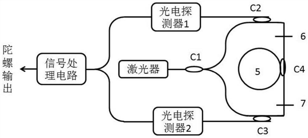
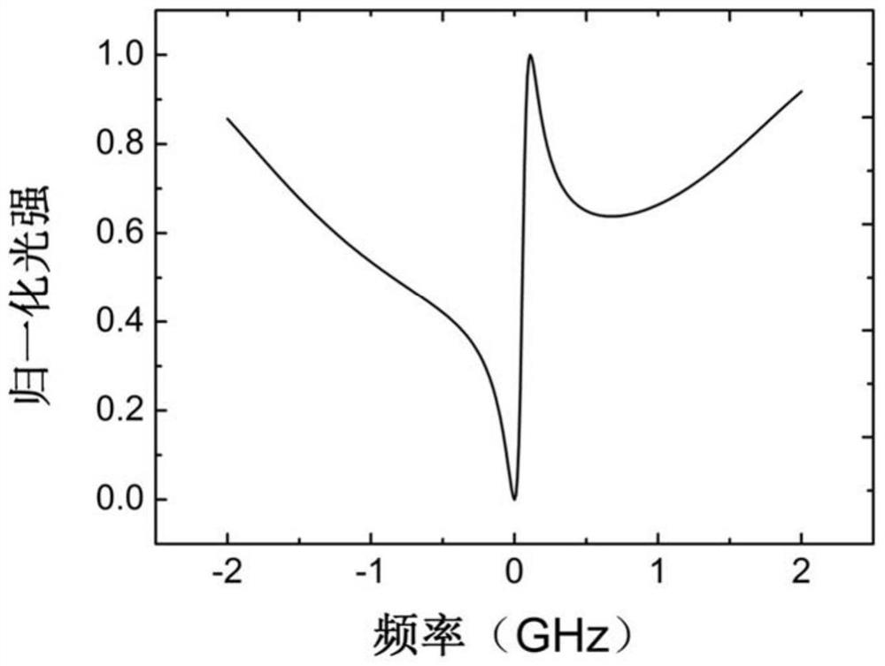
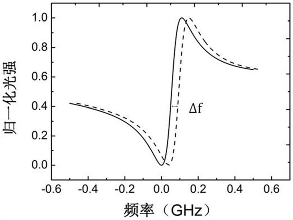
This publicly provides a resonant optical gyroscope based on Funo's resonance effect, including: coupling C1, which is used to divide one laser into the first and second laser beams;First and second laser beams; coupling C4, which is used to receive first and second -direction laser beams, which are the first part of the laser beam through the first part of the reflection unit, and the second part of the laser beam transmitted through the second part of the reflection unit;The resonant cavity is used to receive the beam output by the coupling C4; the coupling C2 and C3 are used to receive the second and one -direction laser beam output by the coupling C4;The second and one direction of laser beams output by C2 and C3 are converted into a electrical signal; and the signal processing circuit is used to perform the processing of processing to determine the rotating angle speed of the optical gyroscope.This publicity simplifies the complexity of the optical gyro system and improves the linearity of the gyro output.

Description

technical field [0001] The present disclosure relates to the technical field of optical sensing and signal detection, in particular to a resonant optical gyroscope based on the Fano resonance effect. Background technique [0002] At present, for optical gyroscopes, the main research direction is how to reduce the size of the device, reduce the manufacturing cost, and improve the integration level. The resonant optical gyro uses the Sagnac effect to detect the rotational angular velocity, which has the advantages of high theoretical precision, easy miniaturization, and anti-vibration. [0003] However, the traditional resonant optical gyroscope detects the rotational angular velocity by detecting the resonant frequency difference of the clockwise and counterclockwise optical paths, which are mainly divided into two types: single-channel locking and double-closed-loop. Usually, a phase modulator is required to modulate the incident light, and complex algorithms are required f...

Claims


Application Information

Patent Timeline
Patent Type & Authority Patents(China)
IPC IPC(8): G01C19/72
Inventor 杨富华费瑶何玉铭李兆峰
Owner INST OF SEMICONDUCTORS - CHINESE ACAD OF SCI
Why Eureka
Eureka Blog
Learn More