
Axel bush

a technology of axel bush and axel, which is applied in the direction of bearing unit rigid support, bearing components, shaft and bearings, etc., can solve the problems of prior art bushes that tend to fail along the joining line, and cannot be slid onto, so as to facilitate the adherence of mold materials

Active Publication Date: 2018-01-23
ROTACASTER WHEEL
View PDF23 Cites 6 Cited by
  • Summary
  • Abstract
  • Description
  • Claims
  • Application Information

AI Technical Summary

Benefits of technology

The patent describes a design for a bush used in a wheel assembly. The bush is made up of two components that are joined together using a curved joining line. The joining line is designed to resist splitting under pressure. The components have engagement sections that are complementary and can engage with each other. The engagement sections are designed to engage with minimal distortion and allow for relative movement between the components without disengaging or causing noise. The design also includes longitudinal ribs that provide strength to the bush and help to control the thickness of the roller material. Overall, the design improves the performance and functionality of the bush in wheel assemblies.

Problems solved by technology

This may also be the case where the axel is non-removably mounted, so that the axel bush cannot be slid onto the axel mounting section as there is no access to the other end of the axel.
However, such prior art bushes tend to fail along the joining line, the so-called coin-purse split or separation of the components along the joining line under pressure.

Method used


Image

  • Axel bush
  • Axel bush
  • Axel bush

Examples


first embodiment

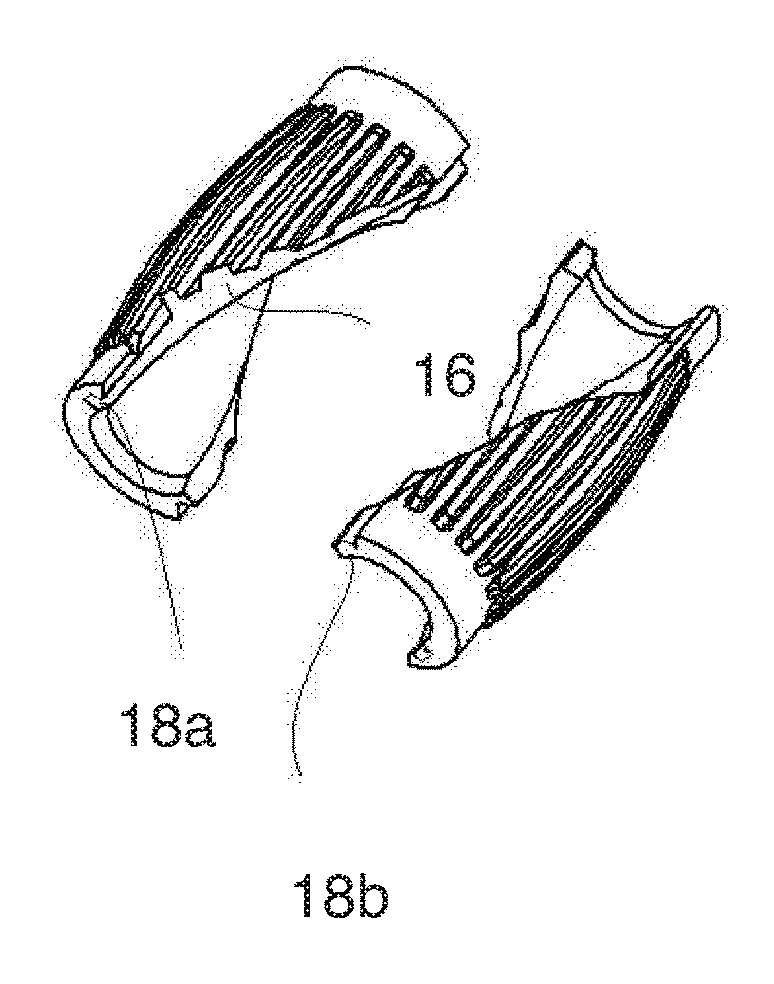
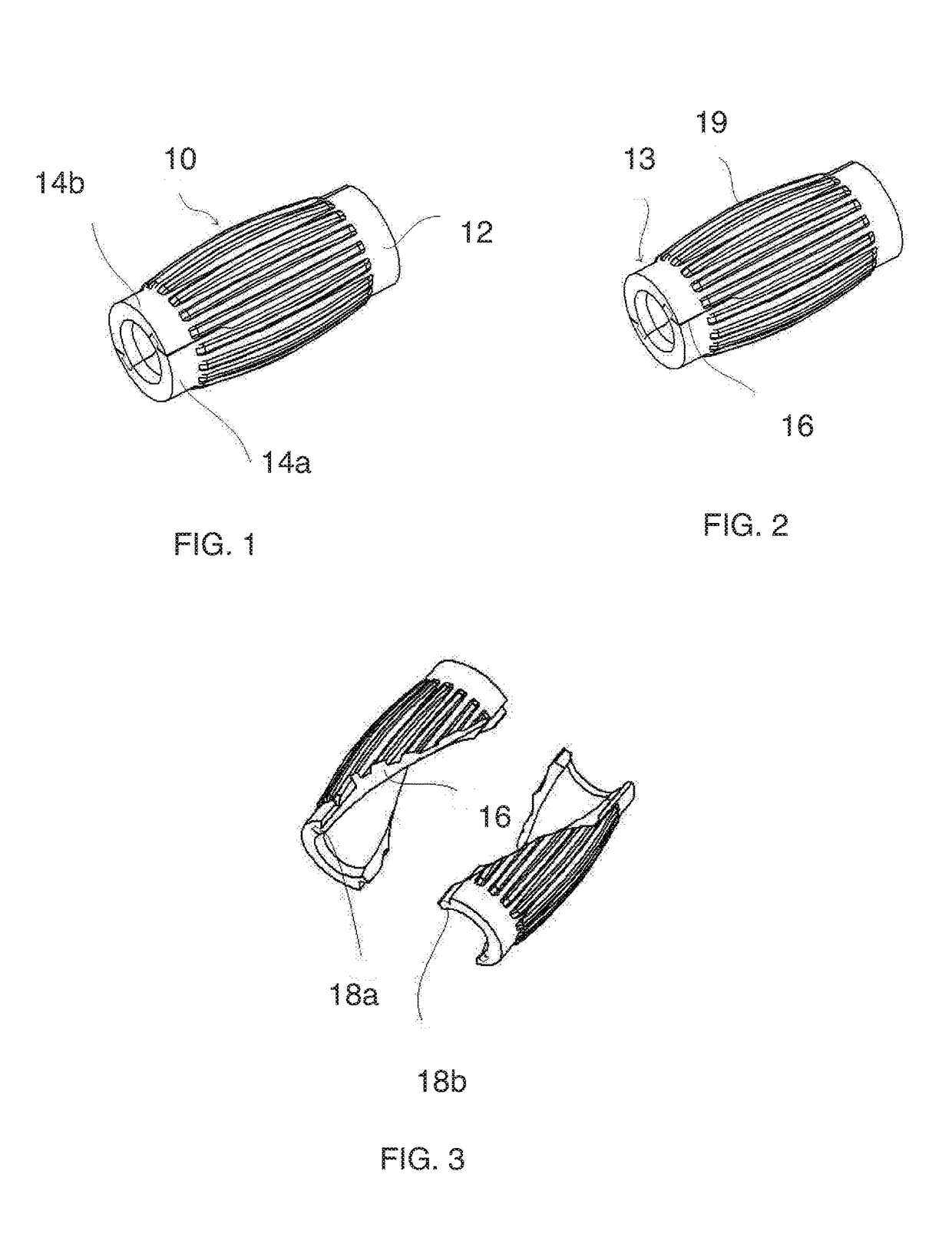
[0078]FIGS. 1-3 show the disclosure in the form of an axel bush 10 comprising a cylindrical core 12, a pair of identical component parts 14a, 14b mated or joined to each other along a pair of helically curved edges 16. The curved edges 16 comprise tongue and groove interconnecting parts 18a, 18b. An outer surface 13 of the cylindrical core 12 has sixteen longitudinally aligned ribs 19.

[0079]Each component part 14a, 14b comprises a pair of helically curving side edges 16 that are perfectly complementary to opposing helically curved edges on the other mating or joining component part 14a, 14b. Each component part 14a, 14b is identical. At one end of the component part 14a, 14b, adjacent the helically curved edge 16, there is a male protruding tongue 18b that extends beyond the flush surface of the helically curved edge 16. At the opposed end of the component part 14a, 14b, the respective helically curved edges 16 terminate with a recess 18a that is complementary to the protrusion 18b....

second embodiment

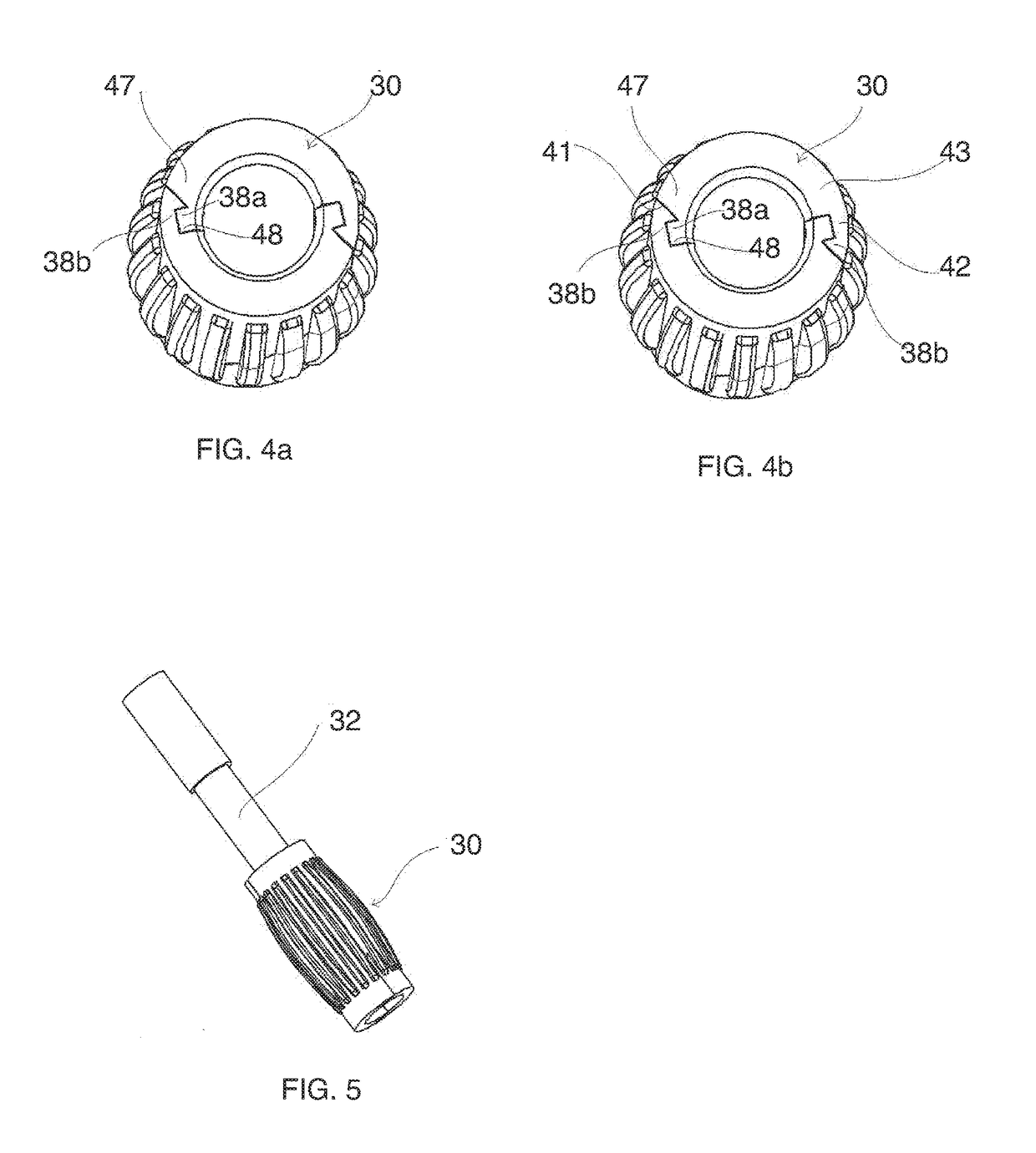
[0080]FIGS. 4-9 show an axel bush 30 made mounted to a wheel frame manufactured and supplied by Rotacaster Wheel Limited. The axel bush may comprise a bayonet catch, 16 outer ribs and a helical joining edge, that are mounted to an axel of a wheel frame of a multiple directional wheel. Prior to assembly, the bush 30 is comprised of two identical halves. The component halves are placed around a cylindrical axel 32 (not shown) mounted and extending between wheel frame head posts 34. A roller (not shown) may then be molded around the axel bush 30 as described in WO 2004014667, the entire contents of which are hereby incorporated herein.

[0081]As shown in FIGS. 4a-9, the axel bush 30 comprises a pair of identical halves 44a, 44b that are adapted to engage together by allowing the engagement of bayonet or arrowhead, or abutting ramp members 38b that comprise an inner inclined ramp surface 41 and a narrow neck 42 that connects the arrowhead or ramp member 38b to the wall of the semi-cylind...

third embodiment

[0082]Referring to FIG. 10, there is shown an axel bush 50 that comprises a substantially cylindrical structure 52 formed of identical component parts 54a, 54b in which the joining line 56 therebetween is formed from a continuous curved edge. The exterior surface of the component parts shows the appearance of the end flat sections that transition between an intermediate angular section with shallow angled corners 58.

[0083]It is noted that the third embodiment does not feature ribs longitudinally on the outer surface of the axel bush 50.


PUM


Abstract

An assembled roller comprising a cylindrical bush having eight external rib surface features and an over-molded roller. The joining edge of the opposing component parts comprises, in axial end profile, a ramp section comprising a ramp surface. The ramp surfaces lie in planes that are parallel or slightly offset by 1° to 20° to the direction or angle of approach of the respective opposed component part immediately prior to engagement, so that the ramp surfaces are adapted to slidingly engage across ramp surfaces in a resistance, rather than snap, fit. This arrangement forms a catch that will hold the component part halves together during an over-molding process as long as the ends of the bush are retarded against axial displacement.

Description

CROSS-REFERENCE TO RELATED APPLICATIONS[0001]This application is a national phase entry under 35 U.S.C. §371 of International Patent Application PCT / AU2013 / 001493, filed Dec. 20, 2013, designating the United States of America and published in English as International Patent Publication WO 2014 / 089642 A1 on Jun. 19, 2014, which claims the benefit under Article 8 of the Patent Cooperation Treaty and under 35 U.S.C. §119(e) to U.S. Provisional Patent Application Ser. Nos. 61 / 915,340, filed Dec. 12, 2013, and 61 / 735,980, filed Dec. 11, 2012, the disclosure of each of which is hereby incorporated herein in its entirety by this reference.TECHNICAL FIELD[0002]This disclosure relates to an axel bush. More particularly, this disclosure relates to an axel bush. More particularly, this disclosure relates to an axel bush for attaching to an axel in situ. Still more particularly, this disclosure relates to an axel bush for an industrial wheel, particularly a multiple directional wheel.BACKGROUND...

Claims


Application Information

Patent Timeline
Patent Type & Authority Patents(United States)
IPC IPC(8): F16C33/02F16C33/04B60B27/00F16C13/00F16C43/02F16C35/02
CPCF16C33/046B60B27/00F16C13/006F16C43/02F16C35/02
Inventor MCKINNON, PETER R.
Owner ROTACASTER WHEEL
Learn More