Method of analyzing seismic data

a seismic data and analysis method technology, applied in seismic signal processing and other directions, can solve the problems of difficult to distinguish diffracted events, difficult to exploit carbonate reservoirs, and noise from migration

Active Publication Date: 2018-01-30
TOTAL PUTEAUX FR
View PDF1 Cites 10 Cited by
  • Summary
  • Abstract
  • Description
  • Claims
  • Application Information

AI Technical Summary

Benefits of technology

[0026]The method limits the migration aperture in the dip-angle domain, which can optimally preserve both specular and non-specular components of the wavefield. It uses a modified Radon transform which can be referred to as Limited Aperture Hybrid Radon Transform (LAHRT).
[0028]In an embodiment, determining the hybrid Radon model associated with the common image gather comprises minimizing an objective function:F(md,mr)=∥Ld·md+Lr·mr−d∥2+εd∥Wd·md∥2+εr∥Wr·mr∥2 where md and mr are data vectors of the diffraction model and of the reflection model, respectively, Ld and Lr are the diffraction and reflection Radon operators, respectively, d represents a data vector of the common image gather, Wd and Wr are model space weights, εd and εr are measures of sparseness for diffraction and reflection, respectively, and ∥·∥2 is an L2 measure.

Problems solved by technology

Carbonate reservoirs are difficult to exploit because of their heterogeneous nature.
A major challenge in carbonate environments is therefore to map these heterogeneities which have a strong impact on oil and gas production.
Typically, diffracted energy is one or even two orders of magnitude weaker than the reflected one and it is not easy to distinguish diffracted events in a seismic dataset or a diffraction image in a seismic image.
When summing the DA-CIGs to assemble the migrated seismic image, the tails of the smile-shaped reflection features are either annihilated in the migrated image due to destructive optimal summation, or they create migration noise due to aliasing in the data and truncation of the migration aperture.
The migrated images obtained after such processing tend to be over-smoothed and they may thus miss small-scale structural features such as fault planes and steps.

Method used


Image

  • Method of analyzing seismic data
  • Method of analyzing seismic data
  • Method of analyzing seismic data

Examples


Embodiment Construction

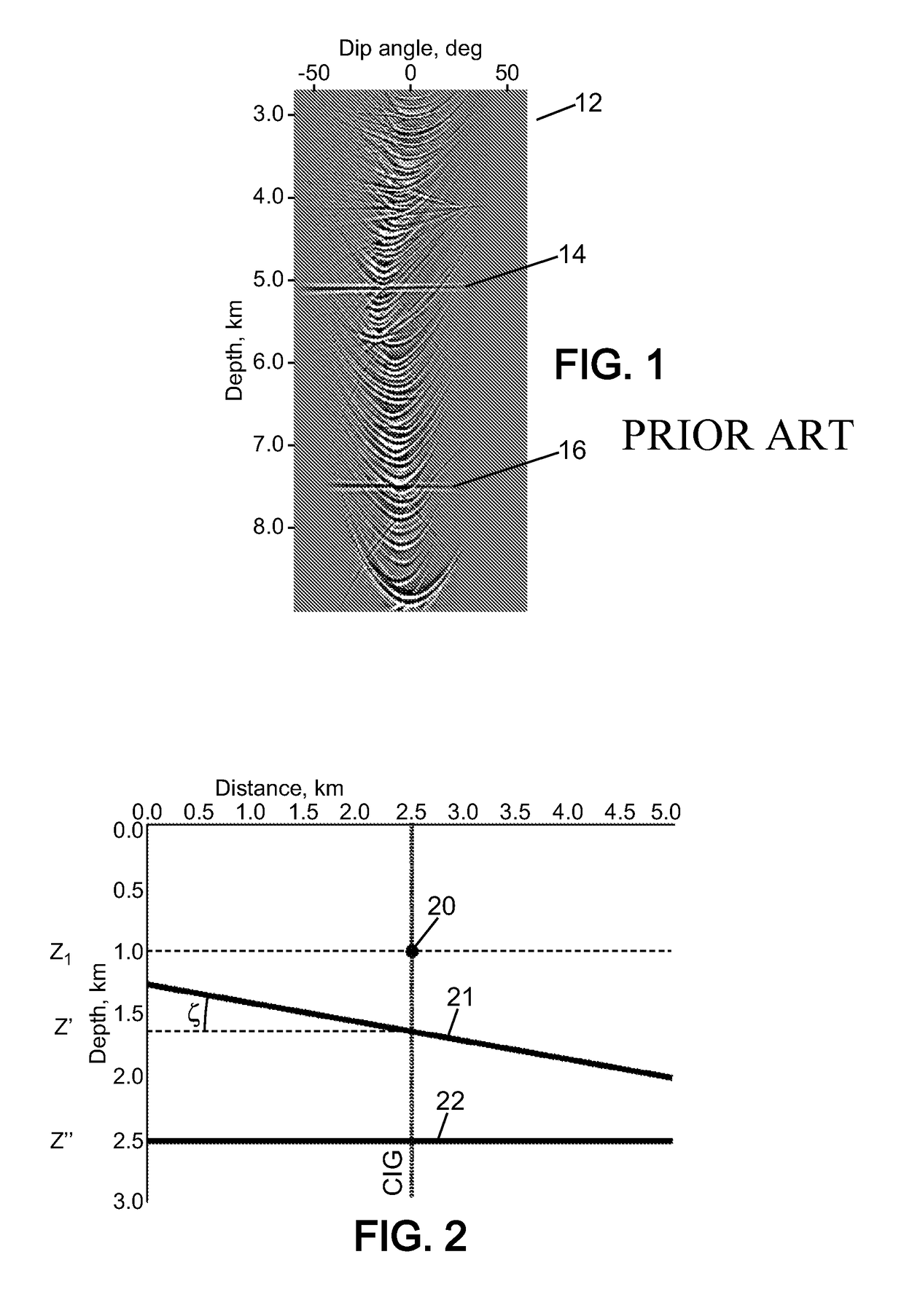
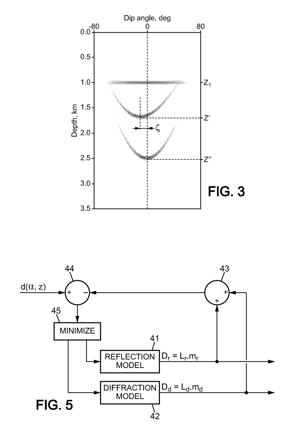
[0048]FIG. 2 is a schematic illustration of the subsurface with a simplified representation of backscattering structures. In this example, at the horizontal position x=2.5 (the y dimension is not shown), a diffractor 20 is at a depth z=z1, and two reflecting surfaces 21, 22 are at depths z=z′ (dip angle α=−ζ) and z=z″ (dip angle α=0). A dip angle common image gather (DA-CIG) at this horizontal position is shown in FIG. 3. It is seen that the diffractor 20 gives rise to a quasi-linear feature at depth z1, while the reflecting structures 21, 22 give rise to respective parabola or smiled-shaped features with apices located at depth z′ and z″. The apex of each parabola is shifted with respect to the position α=0 in the DA-CIG by a value corresponding to the dip angle of the reflecting structure.

[0049]In practice, the subsurface includes numerous reflecting and diffracting structures. So real-world DA-CIGs look much more complex, with many smile-shaped and linear features, and also backg...


PUM


Abstract

Post-migration common image gathers (CIGs) are generated in a dip angle domain from measured seismic data. From a CIG, a hybrid Radon model is determined, including a reflection model related to concave features in the CIG and a diffraction model related to linear features in the CIG. The reflection model is transformed with a reflection Radon operator applied along inversion trajectories restricted around apices of the concave features to obtain reflection data. The diffraction model is transformed with a diffraction Radon operator to obtain diffraction data. The reflection and diffraction data at different horizontal positions can then be combined and summed to generate a migrated image of the subsurface.

Description

PRIORITY CLAIM[0001]The present application is a National Phase entry of PCT Application No. PCT / IB2011 / 000478, filed Feb. 8, 2011, said application being hereby incorporated by reference herein in its entirety.FIELD OF THE INVENTION[0002]The present invention relates a method for analyzing seismic data. More specifically, of geophysical prospecting in areas that contain carbonate reservoirs, i.e. where the hydrocarbon containing rocks are carbonate rocks such as limestone, for example.BACKGROUND OF THE INVENTION[0003]Carbonate reservoirs are difficult to exploit because of their heterogeneous nature. A major challenge in carbonate environments is therefore to map these heterogeneities which have a strong impact on oil and gas production. In many carbonate reservoirs, the porosity of the rock (i.e. matrix porosity) is high enough to contain large amounts of oil in place, but the permeability is mainly provided by fracture corridors, not by the intrinsic nature of the rock matrix. In...

Claims


Application Information

Patent Timeline
Patent Type & Authority Patents(United States)
IPC IPC(8): G01V1/30
CPCG01V1/30
Inventor LANDA, EVGENYBAINA, REDA
Owner TOTAL PUTEAUX FR
Why Eureka
Try Eureka