
Highly retentive automatically skimmable tank

a technology of automatic skimming and high retentiveness, which is applied in the direction of reversed direction vortex, separation process, vortex flow apparatus, etc., can solve the problems of less effective separation of oil and water, less retention time within the tank, and overflow of oil from the tank, so as to prevent shearing and minimize the re-emulsification of oil and water

Active Publication Date: 2018-02-06
KBK IND
View PDF83 Cites 1 Cited by
  • Summary
  • Abstract
  • Description
  • Claims
  • Application Information

AI Technical Summary

Benefits of technology

The water tank has two main functions: to collect and store water, and to filter out oil. The design of the tank is focused on maximizing the time it takes for the water to stay in the tank by controlling the flow of water and allowing it to naturally filter out oil. This allows for a longer retention time, and reduces the amount of oil that needs to be removed on a regular basis. The tank uses a special nozzle and instructions on how to position it to optimize the flow of water and filter out oil based on the natural rotation of the earth.

Problems solved by technology

Current oil skimmer tanks have moving parts that tend to cause problems.
Also, most skimmer tanks require operator activation of oil removal from the tanks which can result in overflow of oil from the tanks.
Additionally, because of the design of the tanks, the flow path of water through the tanks short circuits so that the retention time within the tank is less than optimum.
Less retention time results in less effective separation of oil from the water, with loss of valuable oil and with production of waste water containing more oil-contamination which must be disposed.
The more oil-contamination in the waste water creates a shortened life for waste water disposal wells and increases the cost of disposal.

Method used


Image

  • Highly retentive automatically skimmable tank
  • Highly retentive automatically skimmable tank
  • Highly retentive automatically skimmable tank

Examples


Embodiment Construction

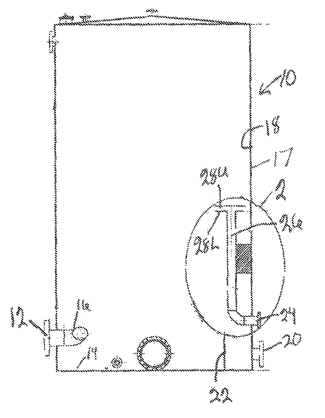
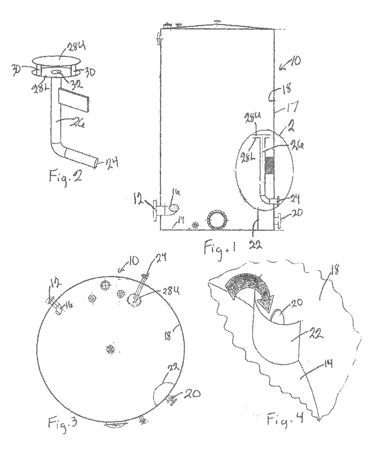
[0028]Referring now to the drawings and initially to FIGS. 1 and 3, there is illustrated a highly retentive automatically skimmable tank 10 that is constructed in accordance with a preferred embodiment of the present invention. The tank 10 is provided with a water inlet nozzle 12 that enters the tank 10 adjacent the bottom 14 of the tank 10. The water inlet nozzle 12 is provided with an extension in the form of a 90 degree long radius elbow 16 that points upward within the tank 10 at approximately a 15 degree angle.

[0029]The 90 degree long radius elbow 16 is turned to the right so the flow is counterclockwise in applications above the earth's equator, and turned to the left so the flow is clockwise in applications below the earth's equator.

[0030]The 90 degree long radius elbow 16 is positioned so the inlet flow is directed at an angle slightly less than parallel to the inside diameter (ID) or inside surface 18 of the tank wall 17 of the tank 10 so the inlet fluid is forced to contac...


PUM

PropertyMeasurementUnit
angleaaaaaaaaaa
angleaaaaaaaaaa
angleaaaaaaaaaa

Abstract

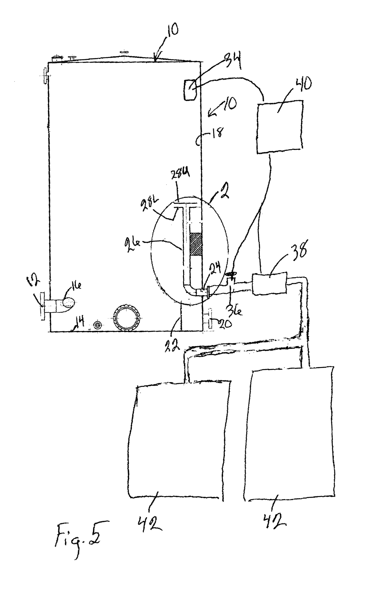
An automatically skimmable tank for removing oil from water. A water inlet with a 90 degree elbow that is turned sideways and points slight upward causes flow to first impinge on the wall of the tank then flow upward helically around the tank's internal diameter (ID) to maximize retention time so that oil separates from the water. At the tank's upper fluid level, the water flows to the center of the tank, then spirals downward to the bottom and under the incoming fluid flow before exiting via the water outlet. Oil is removed from the tank via an upwardly extending oil outlet riser provided with two horizontal anti-vortex plates. A level transmitter senses the oil-gas and the oil-water interfaces and a programmed PLC activates an oil valve and a low shear oil transfer pump to remove oil from the tank when the oil layer surrounds the anti-vortex plates.

Description

BACKGROUND OF THE INVENTION[0001]1. Field of the Invention[0002]The present invention is a skimmer tank for skimming oil from water contained within the tank as it is being used as a water collection or water storage tank. The tank seeks to maximize retention time within the tank and to provide for automatic skimming of oil from the top of the tank without the need for any moving parts within the tank.[0003]2. Description of the Related Art[0004]Current oil skimmer tanks have moving parts that tend to cause problems. Also, most skimmer tanks require operator activation of oil removal from the tanks which can result in overflow of oil from the tanks. Additionally, because of the design of the tanks, the flow path of water through the tanks short circuits so that the retention time within the tank is less than optimum. Less retention time results in less effective separation of oil from the water, with loss of valuable oil and with production of waste water containing more oil-contami...

Claims


Application Information

Patent Timeline
Patent Type & Authority Patents(United States)
IPC IPC(8): C02F1/40C10G33/06B04C3/06B04C5/04C02F101/32
CPCC02F1/40C10G33/06C02F2101/32C02F2209/005C02F2209/42B04C3/06B04C5/04B01D17/12
Inventor BALL, IV, WILL DEXTER
Owner KBK IND
Learn More