Piston for internal combustion engine
a technology for internal combustion engines and pistons, which is applied in the direction of pistons, machines/engines, cylinders, etc., can solve the problems of plate not effectively increasing the flexural rigidity of the head and plate not effectively preventing the formation of cracks in the crown of the piston body, so as to reduce the formation of cracks
- Summary
- Abstract
- Description
- Claims
- Application Information
AI Technical Summary
Benefits of technology
Problems solved by technology
Method used
Image

Examples
first embodiment
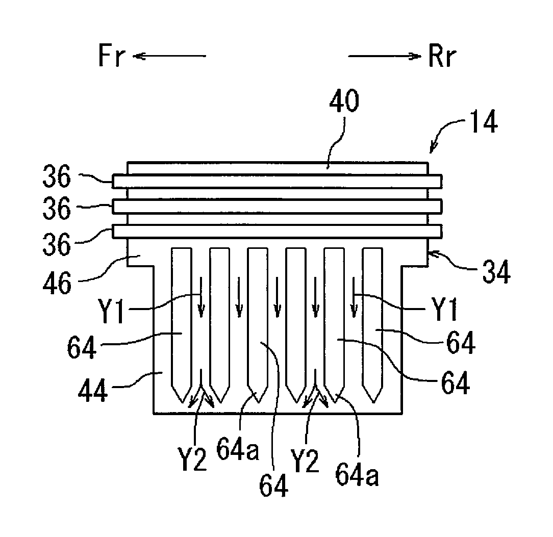
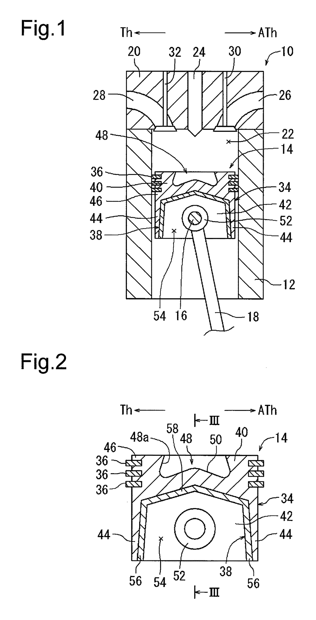
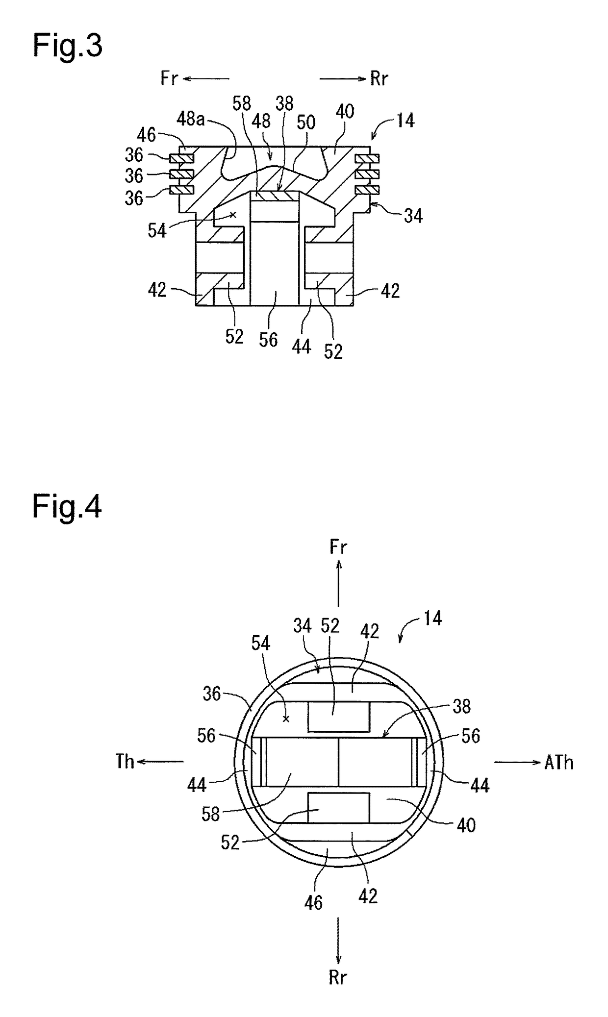
[0022]The present embodiment is applied to a piston 14 for a four-cycle direction injection diesel engine 10 (hereafter referred to as the “diesel engine 10”). FIG. 1 is a cross-sectional view showing a combustion chamber 22 of the engine 10. FIG. 2 is a cross-sectional view showing the piston 14. FIG. 3 is a cross-sectional view taken along line III-III in FIG. 2. FIG. 4 is a bottom view of the piston 14. FIG. 1 shows the piston 14, which is located in one of a plurality of cylinders 12 of the engine 10. In the present specification, the directions in which a piston pin 16 and a crankshaft (not shown) extend are referred to as the engine-front direction (Fr direction) and the engine-rear direction (Rr direction). The directions that are orthogonal to the Fr direction and the Rr direction are referred to as the thrust direction (Th direction) and the anti-thrust direction (ATh direction).
[0023]Referring to FIG. 1, the cylinder 12 accommodates the piston 14 in a manner allowing the p...
second embodiment
[0031]The following description will focus on differences from the first embodiment. FIG. 6 is a perspective view showing a portion of the high-rigidity member 38. As shown in FIG. 6, in the present embodiment, the lower surface of the connecting portion 58 in the high-rigidity member 38 of the first embodiment includes a plurality of (e.g., three) fins 60. Each fin 60 has the form of a rib and extends in the longitudinal direction of the connecting portion 58. Further, each fin 60 has a cross-section in the form of, for example, a reversed triangle. In the piston 14 of the present embodiment, the fins 60 on the lower surface of the connecting portion 58 increase the heat radiation surface and improve the cooling performance of the high-rigidity member 38. This limits decreases in the fatigue strength of the piston body 34 under high temperatures and reduces the formation of cracks in the crown of the piston body 34. The fins 60 of the high-rigidity member 38 increase the section mo...
third embodiment
[0032]The following description will focus on differences from the second embodiment. FIG. 7 is a perspective view showing a portion of the high-rigidity member 38. As shown in FIG. 7, in the present embodiment, the lower surface of the connecting portion 58 in the high-rigidity member 38 includes a vast number of dimples 62 instead of the fins 60 of the second embodiment. Each dimple 62 is concave and has a semispherical wall surface. In the piston 14 of the present embodiment, the dimples 62 in the lower surface of the connecting portion 58 increase the amount of held oil and improve the cooling performance of the high-rigidity member 38. This limits decreases in the fatigue strength of the piston body 34 under high temperatures and reduces the formation of cracks in the crown of the piston body 34.
PUM
| Property | Measurement | Unit |
|---|---|---|
| thickness | aaaaa | aaaaa |
| Young's modulus | aaaaa | aaaaa |
| distance | aaaaa | aaaaa |
Abstract
Description
Claims
Application Information
 - R&D Engineer
- R&D Manager
- IP Professional
- Industry Leading Data Capabilities
- Powerful AI technology
- Patent DNA Extraction
Browse by: Latest US Patents, China's latest patents, Technical Efficacy Thesaurus, Application Domain, Technology Topic.
© 2024 PatSnap. All rights reserved.Legal|Privacy policy|Modern Slavery Act Transparency Statement|Sitemap