
Method for driving liquid crystal display panel

a liquid crystal display and display panel technology, applied in the field of liquid crystal display, can solve the problems that the display effect cannot be improved effectively, the afterimage of the liquid crystal display panel can only be alleviated to a rather limited extent, and achieve the effect of reducing the direct current bias voltage of the subpixel

Active Publication Date: 2018-02-06
TCL CHINA STAR OPTOELECTRONICS TECH CO LTD +1
View PDF10 Cites 0 Cited by
  • Summary
  • Abstract
  • Description
  • Claims
  • Application Information

AI Technical Summary

Benefits of technology

The present patent aims to solve the issue of afterimage in liquid crystal display panels during operation. The method involves regulating the durations of images displayed on the panel to reduce the direct current bias voltage and alleviate the afterimage. By doing so, the driving method becomes more efficient and the afterimage can be effectively reduced. Additionally, the method allows for the reduction or elimination of bias voltage in sub pixels through the regulation of image frames. The method can be applied to both dynamic and still images displayed on the panel, improving the driving and display efficiency.

Problems solved by technology

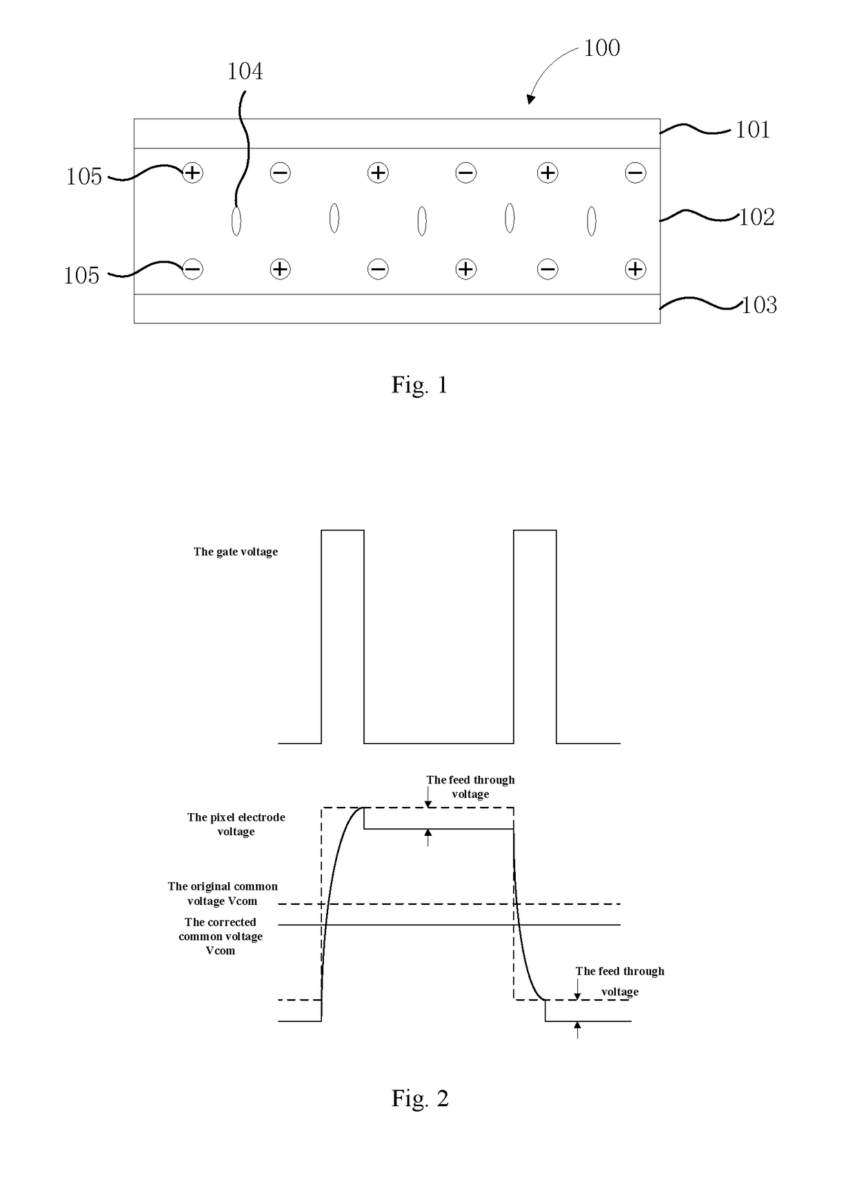
However, there would still be a certain direct current bias voltage in different liquid crystal display panels and different areas of the same liquid crystal display panel after long time driving because of the differences of the manufacturing process, signal transmission loss, human-caused error, and other factors.
However, according to the methods in the prior art, the afterimage of the liquid crystal display panel can only be alleviated to a rather limited extent, and the display effect thereof cannot be improved effectively.

Method used


Image

  • Method for driving liquid crystal display panel
  • Method for driving liquid crystal display panel
  • Method for driving liquid crystal display panel

Examples


embodiment 1

[0065]If the liquid crystal display panel is driven in the conventional isochronous driving method, the common voltage should be reduced to a certain extent in order to avoid an excessive direct current. However, when the common voltage is reduced, a positive direct current bias voltage would exist in some sub pixels after a period of operation. The positive direct current bias voltage needs to be neutralized or reduced in order to eliminate or alleviate the afterimage.

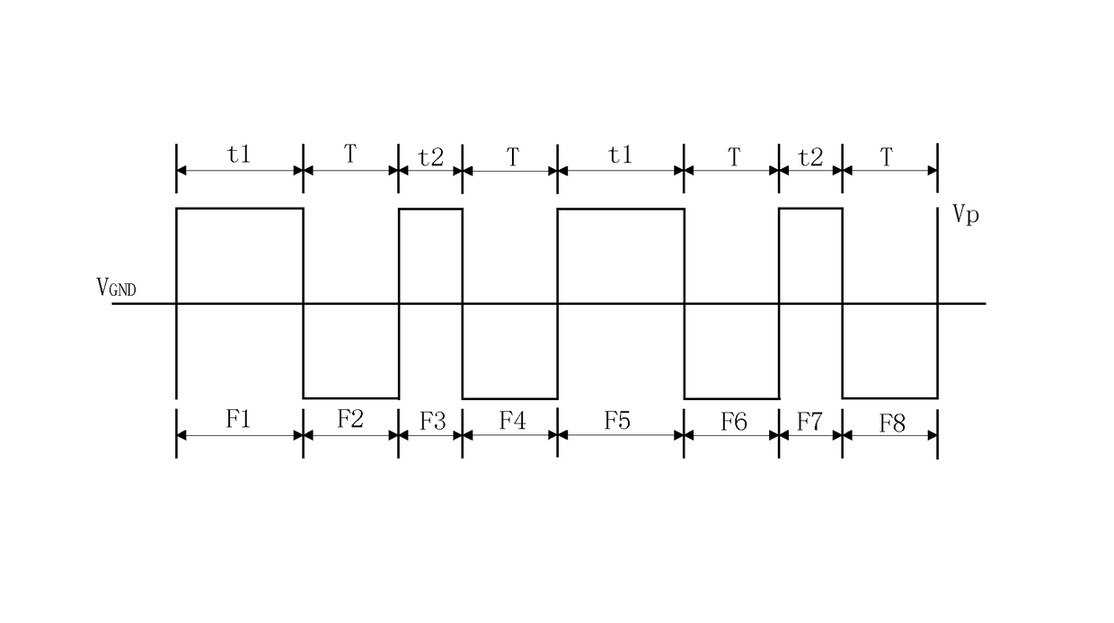
[0066]According to the driving method provided by the present embodiment, the durations of the image frames are regulated, so that the duration of the image frame in which the voltage difference between the pixel electrode and the common electrode of the sub pixel is negative (referred to as “negative image frame” hereinafter) is prolonged relatively, or the duration of the image frame in which the voltage difference between the pixel electrode and the common electrode of the sub pixel is positive (referred to as “pos...

embodiment 2

[0083]If the liquid crystal display panel is driven in the conventional isochronous driving method, the common voltage should be reduced to a certain extent in order to avoid an excessive direct current. However, when the common voltage is reduced, a negative direct current bias voltage would exist in some sub pixels after a period of operation.

[0084]The negative direct current bias voltage needs to be neutralized or reduced in order to eliminate or alleviate the afterimage. According to the driving method provided by the present embodiment, the durations of the image frames are regulated, so that the duration of the image frame in which the voltage difference between the pixel electrode and the common electrode of the sub pixel is positive (referred to as “positive image frame” hereinafter) is prolonged relatively, or the duration of the image frame in which the voltage difference between the pixel electrode and the common electrode of the sub pixel is negative (referred to as “neg...

embodiment 3

[0087]According to the present embodiment, based on the method provided by embodiment 1 or embodiment 2, and with the cooperation of two adjacent data lines, the polarity of the direct current bias voltage of one data line can be arranged opposite to the polarity of the direct current bias voltage of another data line of the two adjacent data lines. In this manner, a voltage difference would exist between the two data lines, and the impurities in the panel can be effectively adsorbed by the voltage difference. Therefore, the extent that the impurities accumulate on the two sides of the liquid crystal display panel can be reduced, and the afterimage thereof can be alleviated.

[0088]Specifically, according to the present embodiment, with respect to a first sub pixel and a second sub pixel that are arranged on adjacent data lines respectively, a polarity of a voltage difference of a pixel electrode and a common electrode of the first sub pixel can be arranged to be opposite to that of t...


PUM


Abstract

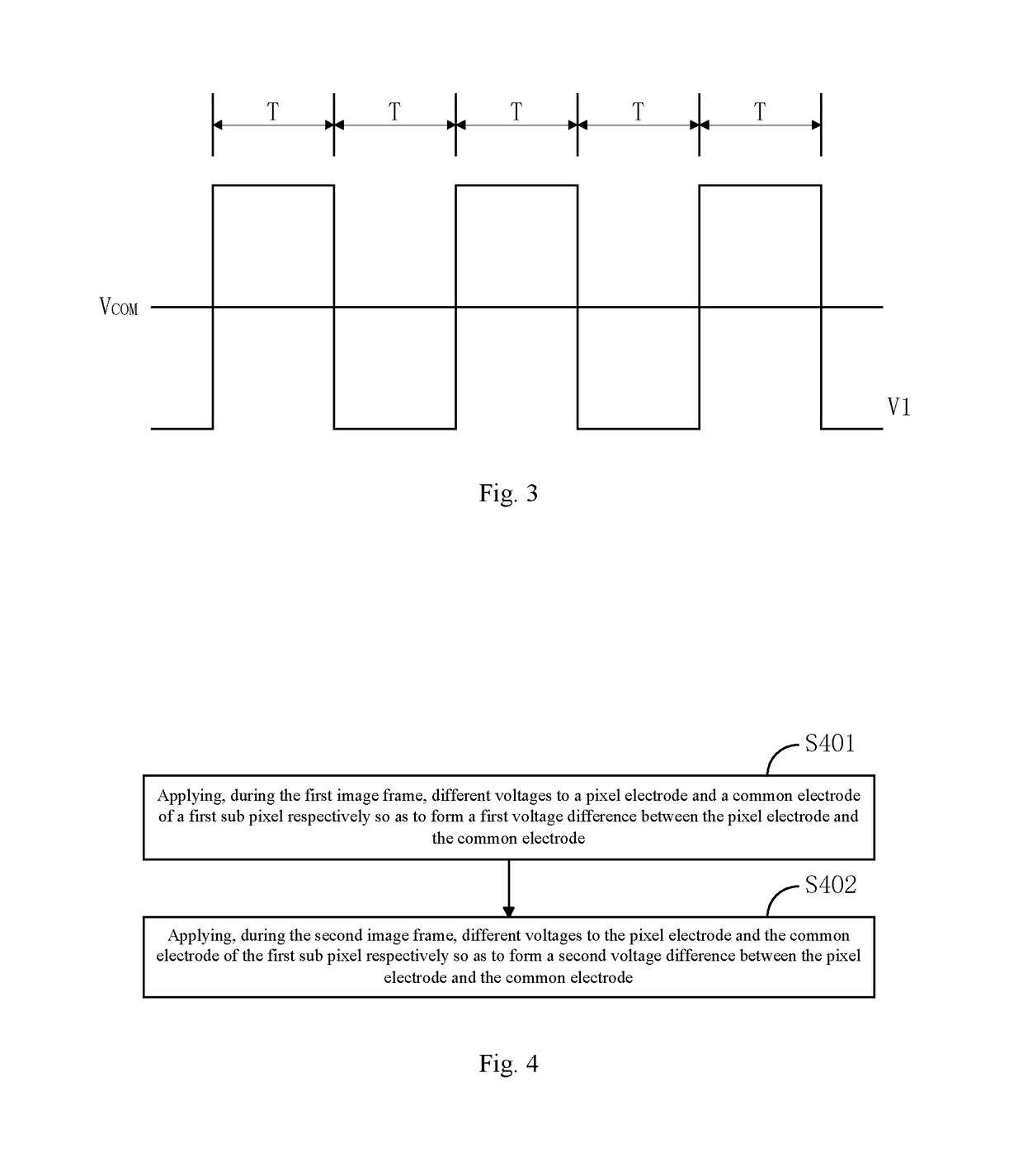
A method for driving a liquid crystal display panel is disclosed. The liquid crystal display panel comprises a plurality of sub pixels, and the method comprises presenting images to be displayed on the liquid crystal display panel frame by frame through regulating a gray-scale of each sub pixel of the liquid crystal display panel, wherein durations of image frames are not all equal to one another so as to reduce a direct current bias voltage of the sub pixel. According to the method, the direct current bias voltage during the isochronous driving process can be effectively reduced, and thus the afterimage of the liquid crystal display panel can be alleviated.

Description

CROSS REFERENCE TO RELATED APPLICATION[0001]The present application claims benefit of Chinese patent application CN 201510314145.3, entitled “Method for Driving Liquid Crystal Display Panel” and filed on Jun. 9, 2015, the entirety of which is incorporated herein by reference.FIELD OF THE INVENTION[0002]The present disclosure relates to the technical field of liquid crystal display, and particularly to a method for driving a liquid crystal display panel.BACKGROUND OF THE INVENTION[0003]Compared with the Cathode-Ray Tube (CRT) display devices that are widely used in early stage, the Liquid Crystal Displays (LCDs) have the advantages of a light and thin structure, low driving voltage, and low power consumption. Therefore, the LCD devices, especially the active array LCDs are widely used in various electronic apparatuses. In the active array LCD, Thin Film Transistors (TFTs) are arranged to serve as the switching elements for the sub pixels, and enable that the display performance of th...

Claims


Application Information

Patent Timeline
Patent Type & Authority Patents(United States)
IPC IPC(8): G09G3/36
CPCG09G3/3607G09G3/3614G09G2310/08G09G2310/0243G09G2300/0443G09G2320/0204G09G2320/0219G09G2340/0435
Inventor TANG, YUEJUN
Owner TCL CHINA STAR OPTOELECTRONICS TECH CO LTD
Learn More