Attachment method for laminate structures

a technology of laminate structure and attachment method, which is applied in the direction of manufacturing tools, other domestic objects, non-electric welding apparatus, etc., can solve the problems of difficulty in other material combinations, difficulty in weldability, and general consideration of material not so easily weldable, so as to achieve the effect of preserving strength and saving weigh

Active Publication Date: 2018-02-13
HONDA MOTOR CO LTD
View PDF35 Cites 2 Cited by
  • Summary
  • Abstract
  • Description
  • Claims
  • Application Information

AI Technical Summary

Benefits of technology

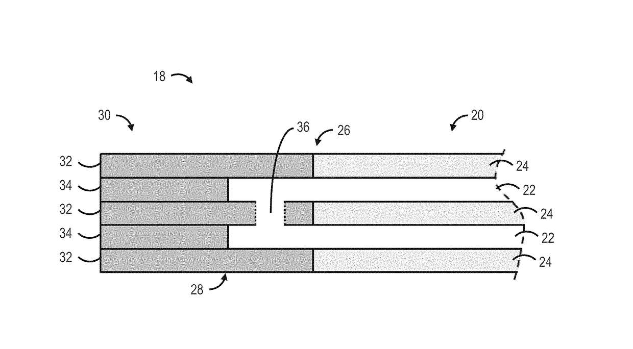
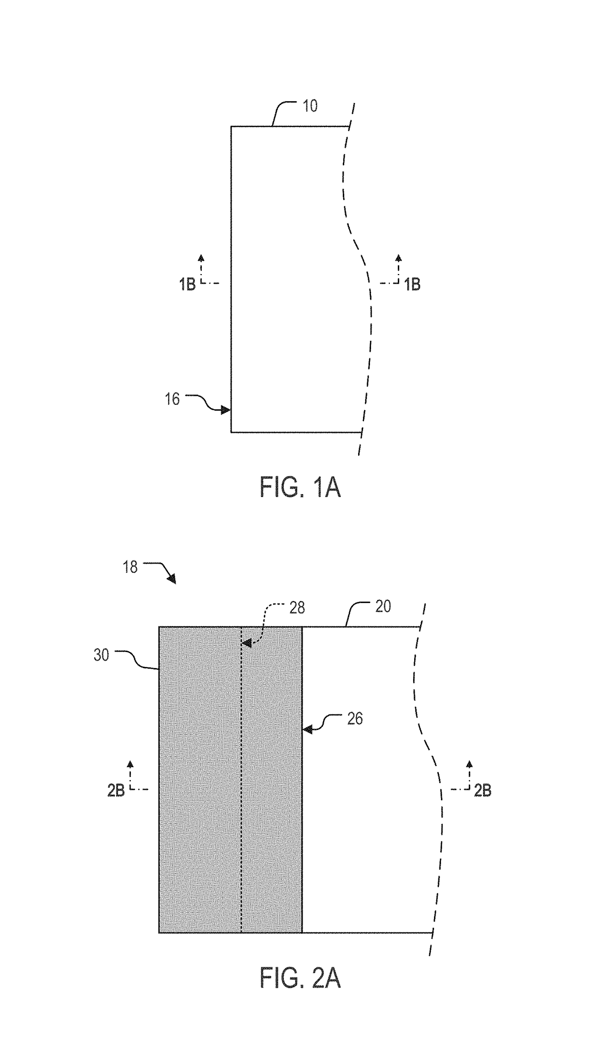
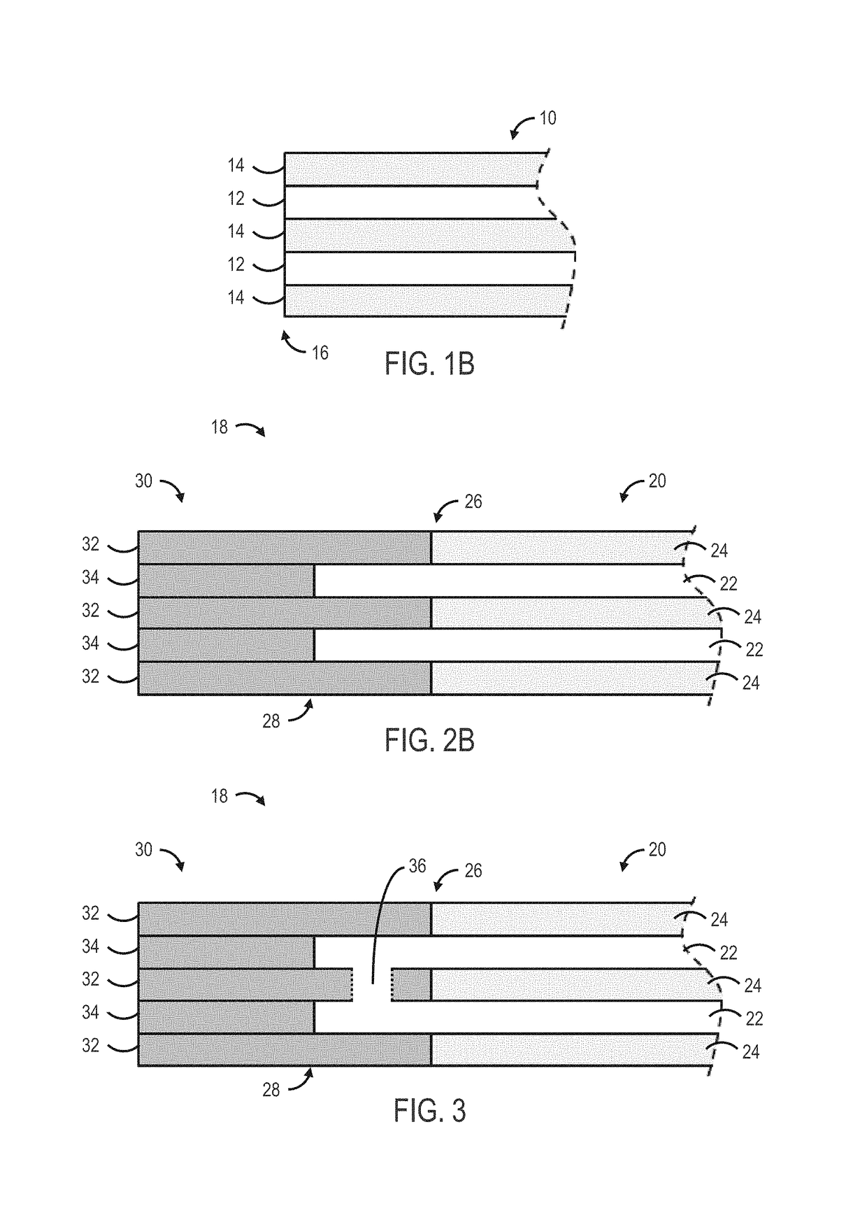
[0014]The present disclosure overcomes the aforementioned drawbacks by providing a laminates structure with a laminate body and a flanged end piece. In one example, a steel edge is incorporated into a laminate structure by layering steel within the structure, but only on the edge. The steel layers will bond to each other and the other material within the laminate will be imbedded within the steel edge. This allows for retention of strength and weight savings provided by the laminate while creating the ability to directly attach the structure to any other steel part using traditional methods such as welding.

Problems solved by technology

If special precautions, such as preheating, specified heat input, controlled cooling, and postheating are required, the material generally is considered not so easily weldable.
While certain combinations of materials can be joined relatively easily via welding, other material combinations can prove to be more difficult.
Generally, challenges may arise if the combined metallurgy of each of the original materials prevents the production of sound joints.
Unsound joints result from differences in melting temperatures, lack of appreciable solubility of either metal in the other in the solid state, and formation of brittle intermetallic compounds.
In one example, welding of either titanium or aluminum with other metals such as steel can be difficult due to issues such as embrittlement caused by the formation of intermetallic phases.
Attempts to weld such materials without the use of specialized techniques generally results in welds of limited ductility.
In the particular case of steel and titanium, the low solubility of iron in alpha titanium at room temperature results in a weld wherein the resulting intermetallic phases (i.e., TiFe and TiFe2) are very hard and brittle, thereby preventing the production of functional welds.
Issues with forming suitable welds between work pieces or material can also arise for laminates.
Although there is a variety of material combinations used in the formation of laminates, oftentimes the resulting laminate structure cannot be directly welded to traditional steel.
As a result, it may be difficult to incorporate laminates into structures of which the majority of the structural components are steel.
However, more specialized techniques are required to use a welding technique to bond two or more incompatible materials.
One drawback is that care must be taken to avoid overheating of the insert during welding, which can result in undesirable brittle intermetallic compounds at the interface of the transition insert.
Moreover, the selection of a transition insert is further complicated when one of the work pieces to be welded is a heterogeneous laminate.
However, this process also has a number of drawbacks as certain precautions must still be taken during the welding process.
Nevertheless, coating type joint methods are usually used for sealing purposes only and are generally not applicable when is desirable to achieve a full mechanical strength joint.

Method used


Image

  • Attachment method for laminate structures
  • Attachment method for laminate structures
  • Attachment method for laminate structures

Examples


Embodiment Construction

[0034]The present disclosure is presented in several varying embodiments in the following description with reference to the Figures, in which like numbers represent the same or similar elements. Reference throughout this specification to “one embodiment,”“an embodiment,” or similar language means that a particular feature, structure, or characteristic described in connection with the embodiment is included in at least one embodiment of the present disclosure. Thus, appearances of the phrases “in one embodiment,”“in an embodiment,” and similar language throughout this specification may, but do not necessarily, all refer to the same embodiment.

[0035]The described features, structures, or characteristics of the disclosure may be combined in any suitable manner in one or more embodiments. In the following description, numerous specific details are recited to provide a thorough understanding of embodiments of the system. One skilled in the relevant art will recognize, however, that the s...


PUM

PropertyMeasurementUnit
widthaaaaaaaaaa
thickaaaaaaaaaa
thickaaaaaaaaaa

Abstract

The present disclosure provides a laminate structure including a laminate body with a second ply positioned between a first ply and a third ply, the second ply having an edge extending outward from a corresponding edge of the first and third plies. The laminate structure further includes a flange positioned on the edge of the second ply. The flange includes a first finger and a second finger extending outward to define a receptacle that receives the edge of the second ply therein.

Description

CROSS-REFERENCE TO RELATED APPLICATIONS[0001]This application is based on, claims the benefit of, and incorporates herein by reference U.S. Provisional Application Ser. No. 61 / 978,128 filed on Apr. 10, 2014.STATEMENT REGARDING FEDERALLY SPONSORED RESEARCH[0002]Not applicable.BACKGROUND OF THE INVENTION[0003]The disclosure relates, in general, to methods for joining incompatible materials, and more particularly to a system and method for enabling laminates to be welded to traditional materials such as steel.[0004]Welding is a process in which two or more work pieces are joined by transforming at least one of the work pieces and, optionally, a filler material into a molten state to provide a weld pool. The weld pool is then cooled to form a strong bond or joint between the work pieces. In one aspect, this joining process can additionally involve heat, pressure or a combination thereof. Examples of materials that can be joined through welding include metals such as steel, aluminum, cop...

Claims


Application Information

Patent Timeline
Patent Type & Authority Patents(United States)
IPC IPC(8): B21K23/04B23K20/02B23K20/227B23K20/22B32B3/26C22C14/00B32B15/01
CPCB32B15/017B23K20/02B23K20/22B23K20/2275C22C14/00B32B15/01B32B15/011B32B15/013B32B15/015B32B3/266
Inventor MILLER, RYAN A.
Owner HONDA MOTOR CO LTD
Why Eureka
Try Eureka