Anti-siphon arrangement for hydraulic systems

a hydraulic system and anti-siphon technology, applied in mechanical equipment, gearing details, machines/engines, etc., can solve the problems of reducing the fluid level in the reservoir, affecting system performance, and suffering from siphoning or leakage of fluid out of the reservoir

Active Publication Date: 2018-02-13
DEERE & CO
View PDF33 Cites 2 Cited by
  • Summary
  • Abstract
  • Description
  • Claims
  • Application Information

AI Technical Summary

Benefits of technology

[0008]According to one aspect of the disclosure, an anti-siphon arrangement may include first and second flow paths providing hydraulic communication between a reservoir and at least one area below an oil level of the reservoir. Each of the two flow paths may include an anti-siphon portion extending at least partly above the oil level of the reservoir. First and second valves may be configured, when open, to allow gas to flow from at least one gas source to the respective first and second anti-siphon portions of the two flow paths. Opening the first and second valves may accordingly prevent siphoning of fluid from the first reservoir to the area through, respectively, the first and second flow paths.

Problems solved by technology

Configurations with elevated reservoirs, however, may suffer from siphoning or leakage of fluid out of the reservoirs.
Among other issues, this can result in reduced fluid levels in the reservoirs, which may be detrimental to system performance.
For example, in lubrication systems for vehicle transmissions, excessive siphoning of oil from a main sump may require a delay in starting the vehicle or engaging the transmission until the sump has been adequately primed or may result in increased parasitic loads due to a dry sump being filled with siphoned or leaked oil.
Due to unavoidable leakage, however, siphoning may still cause the reservoirs to lose fluid, in aggregate, when the pumps are not active.

Method used


Image

  • Anti-siphon arrangement for hydraulic systems
  • Anti-siphon arrangement for hydraulic systems
  • Anti-siphon arrangement for hydraulic systems

Examples


Embodiment Construction

[0018]The following describes one or more example embodiments of the disclosed anti-siphon arrangement, as shown in the accompanying figures of the drawings described briefly above. Various modifications to the example embodiments may be contemplated by one of skill in the art.

[0019]As used herein, a “reservoir” may refer to an area that is sufficiently bounded for fluid to accumulate. A “reservoir” may include, for example, tanks and other containers, enclosed or open sumps or catchment areas, partially bounded areas in cases or housings, and so on.

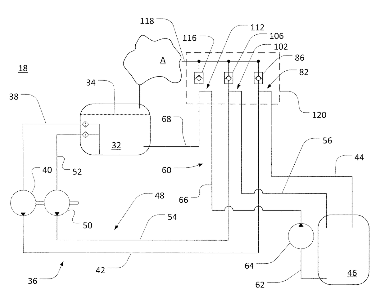
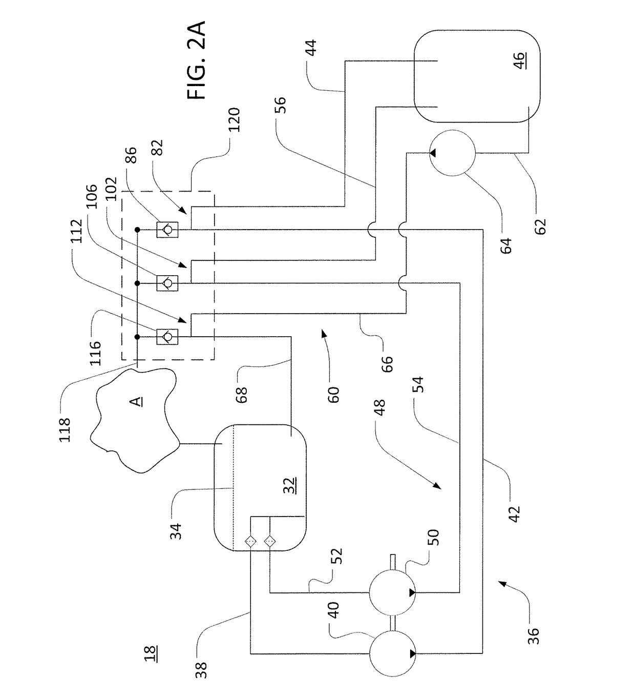
[0020]Also as used herein, a “flow path” may be viewed as an arrangement of one or more components to provide fluid communication between two areas. A flow path may sometimes include one or more flow lines (e.g., flexible hoses, piping, channels, and so on) to transmit pressurized fluid over a distance. Some flow paths may include one or more pumps, manually and automatically controlled valve assemblies, filters or other hydraulic compon...


PUM


Abstract

An anti-siphon arrangement for a hydraulic system with a reservoir includes first and second flow paths providing hydraulic communication between the reservoir and a lower area. Each flow path includes an anti-siphon portion extending at least partly above a fluid level of the reservoir. First and second valves are configured, when configured in open states, to allow gas to flow from a gas source to the anti-siphon portions of the first and second flow paths, respectively.

Description

CROSS-REFERENCE TO RELATED APPLICATION(S)[0001]Not applicable.STATEMENT OF FEDERALLY SPONSORED RESEARCH OR DEVELOPMENT[0002]Not applicable.FIELD OF THE DISCLOSURE[0003]This disclosure relates to arrangements for blocking siphoning or leakage flow in hydraulic systems, including lubrication, cooling, and charge systems for work vehicles.BACKGROUND OF THE DISCLOSURE[0004]In hydraulic systems, a reservoir of fluid is sometimes placed in hydraulic communication with an area of relatively lower elevation. This may be useful, for example, to lubricate, cool, control, or charge components of a vehicle drive train with oil from a sump that is disposed at a higher elevation than the components to be lubricated or cooled. Configurations with elevated reservoirs, however, may suffer from siphoning or leakage of fluid out of the reservoirs. Among other issues, this can result in reduced fluid levels in the reservoirs, which may be detrimental to system performance. For example, in lubrication s...

Claims


Application Information

Patent Timeline
Patent Type & Authority Patents(United States)
IPC IPC(8): F16H57/04F15B20/00F15B1/26F15B21/04F01M1/12E02F9/22F16H57/02F15B21/044
CPCF16H57/0436F16H57/0435F16H57/0452E02F9/226F16H2057/02056F15B1/26F15B20/005F15B21/044F01M2001/123
Inventor GARDNER, MICHAEL L.MARVIN, PAUL D.
Owner DEERE & CO
Why Eureka
Try Eureka