FCC catalyst cyclone sampling method and apparatus

a catalyst cyclone and sampling method technology, applied in the field of fcc catalyst cyclone sampling method and apparatus, can solve the problems of increasing catalyst splashing and partially blocking the view of users, and achieve the effects of reducing or eliminating the risk of catalyst splashing, safely monitoring the level of the sampling can, and eliminating catalyst splashing

Active Publication Date: 2018-02-13
MARATHON PETROLEUM
View PDF8 Cites 7 Cited by
  • Summary
  • Abstract
  • Description
  • Claims
  • Application Information

AI Technical Summary

Benefits of technology

[0008]By upgrading the current sampling line to include a cyclone many of the risks may be greatly reduced or eliminated altogether. The cyclone sampler allows the catalyst to be directed straight into a sampling can, virtually eliminating catalyst splashing and allowing the operator to safely monitor the level of the sampling can, and the flow of the catalyst. The cyclone sampler eliminates the need for the sampling line to descend horizontally. Traditionally the sampling line is slopped to allow the catalyst to enter a sampling can and to reduce pluggage. This slope causes the sampling line to enter the sampling can at angle. This angled entry results in increased splashing and partially blocks the view of the user. The cyclone sampler allows the sampling line to be horizontal, from the FCC to the cyclone sampler. The catalyst enters the cyclone sampler and is directed downward, generally at about a 90-degree angle, into the sampling can. This straight approach allows more of the sample to enter the sampling can and reduces splashing over the prior art model, while allowing the user an unobstructed view of the sampling can.
[0009]The cyclone sampler also allows the operator to use a nitrogen “chaser” further reducing the risk of pluggage in the sample line and cooling the catalyst sample. The nitrogen can be used to purge the sample line, once the sample valve is closed, without spraying the catalyst uncontrolled into the sample can. The chaser is directed into the cyclone sampler and exits into the sampling can at the same 90-degree angle as the catalyst, thus reducing splashing.
[0010]The cyclone sampler also eliminates operator exposure to catalyst and catalyst dust by containing and directing the catalyst so that catalyst dust is greatly reduced in the area around the sample station. Further, utilizing a cyclone sample allows the catalyst to cool while in the cyclone vessel reducing risk of personnel exposure to 1300° F. catalyst. By utilizing a cyclone sampler, operator safety is increased while the risk of pluggage is reduced.

Problems solved by technology

This angled entry results in increased splashing and partially blocks the view of the user.

Method used


Image

  • FCC catalyst cyclone sampling method and apparatus
  • FCC catalyst cyclone sampling method and apparatus
  • FCC catalyst cyclone sampling method and apparatus

Examples


Embodiment Construction

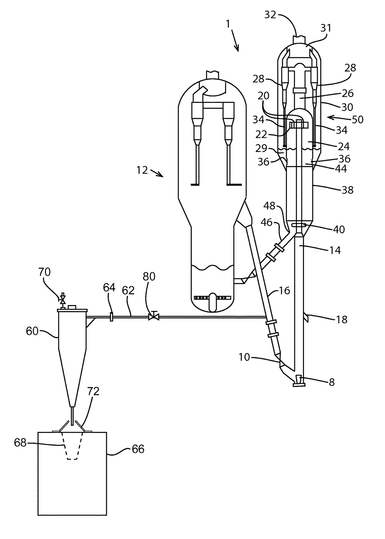
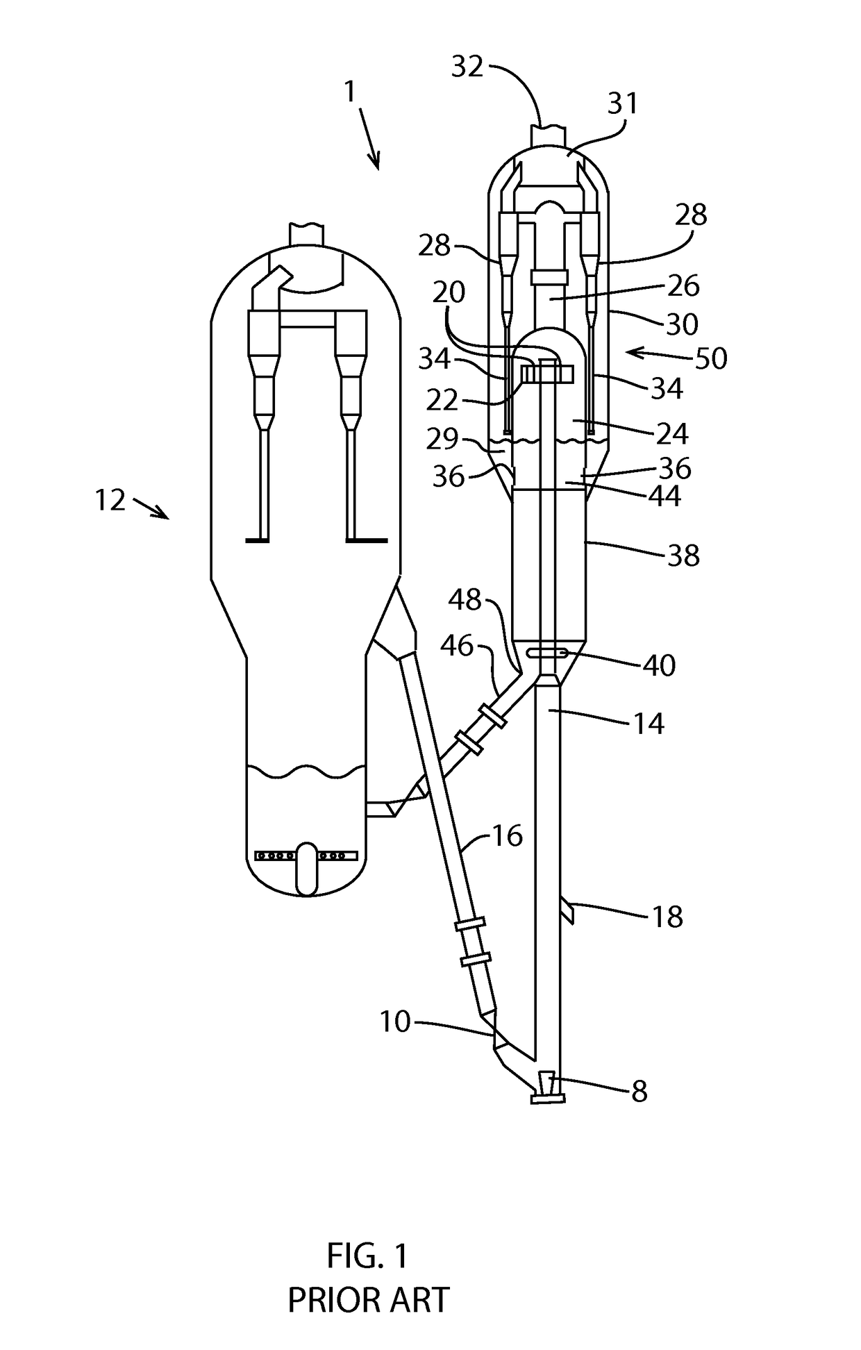
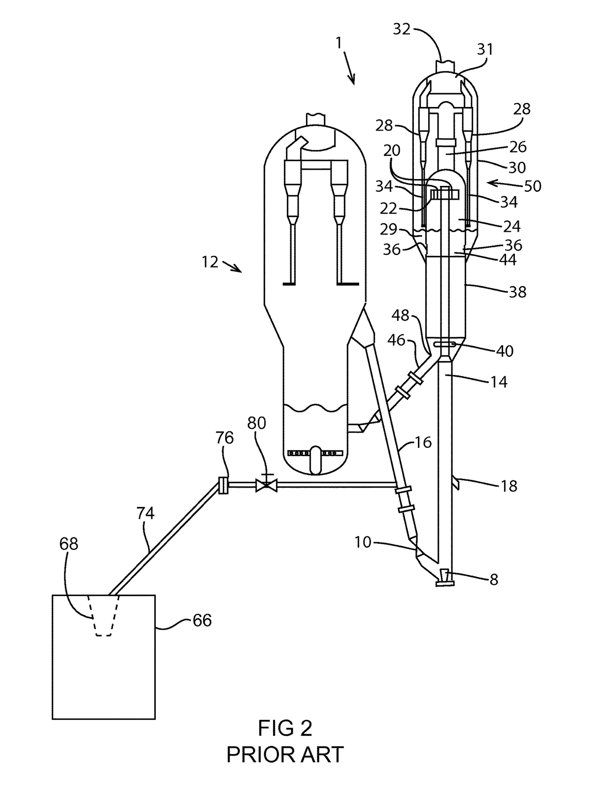
[0017]Referring now to FIG. 1, a catalytic cracking unit 1 is shown and is comprised of a regenerator 12, and a reactor 50. Catalyst is transferred from the regenerator 12 to the reactor 50 by a regenerator catalyst stand pipe 16. The rate of catalyst transfer from the reactor 50 to the regenerator 12 is regulated by a slide valve 10. A fluidization medium from nozzle 8 transports catalyst upwardly through a lower portion of a riser 14 at a relative high density until a plurality of feed injection nozzles 18 (only one is shown) inject feed across the flowing stream of catalyst particles. The resulting mixture continues upward through an upper portion of riser 14 to a riser termination device. This specific device utilizes at least two disengaging arms 20 which tangently discharge the mixture of gas and catalyst through openings 22 from a top of riser 14 into disengaging vessel 24 that effects separation of gases from the catalyst. Most of the catalyst discharged from opening 22 fall...


PUM

PropertyMeasurementUnit
velocityaaaaaaaaaa
temperatureaaaaaaaaaa
molecular weightaaaaaaaaaa

Abstract

A method and apparatus for sampling fluid catalytic cracking catalyst wherein catalyst splashing is virtually eliminated, pluggage is reduced, and the temperature and velocity of the catalyst is also reduced.

Description

CROSS REFERENCE TO RELATED APPLICATION[0001]The present patent application is a divisional of and claims the benefit of U.S. provisional patent application No. 61 / 910,607 filed Dec. 2, 2013.BACKGROUND OF THE INVENTION[0002]Fluid catalytic cracking (FCC) is a vital process used in the refining of petroleum products. The majority of the refineries in use today utilize the FCC process. Fluid catalytic cracking is used to convert the high boiling, high molecular weight hydrocarbon fractions of petroleum crude oils to more valuable gasoline, olefinic gases and other petroleum products. The FCC process vaporizes and breaks the long-chain molecules of the high boiling hydrocarbon liquids into much shorter molecules by contacting the feedstock at elevated temperatures and pressure in the presence of a catalyst, with the majority of the cracking occurring in the vapor phase. Feedstock is thereby converted into gasoline, distillate, and other liquid cracking products as well as lighter gaseou...

Claims


Application Information

Patent Timeline
Patent Type & Authority Patents(United States)
IPC IPC(8): G01N1/10F17D3/01
CPCF17D3/01F17D3/10
Inventor HIGHFIELD, JR., JOHNNY M.WALLACE, BARTON A.NOTT, JEREMY C.
Owner MARATHON PETROLEUM
Why Eureka
Try Eureka