Backlight module and liquid crystal display apparatus

a liquid crystal display and backlight module technology, applied in the field of backlight modules and liquid crystal display apparatuses, can solve the problems of reducing the adhesion strength of square-shaped adhesive tape, affecting display quality, and lack of plastic frame structure, so as to reduce assembly tolerance and enhance cutting ability.

Active Publication Date: 2018-02-13
WUHAN CHINA STAR OPTOELECTRONICS TECH CO LTD
View PDF5 Cites 0 Cited by
  • Summary
  • Abstract
  • Description
  • Claims
  • Application Information

AI Technical Summary

Benefits of technology

[0008]The present invention provides a backlight module having a square-shaped adhesive tape which reaches a standard minimum width for cutting and still helps achieving frame slimming without the need of enhancing cutting ability and reducing assembling tolerance.
[0046]The advantages of the present invention are: the backlight module and the liquid crystal display apparatus provided by the present invention mainly form a transitional surface at an edge of a plastic frame where an excessive portion of a square-shaped adhesive tape can be adhered on the transitional surface so that the excessive portion of the square-shaped adhesive tape would not extend outwardly from the plastic frame; in the meantime, the adhesion strength of the square-shaped adhesive tape is ensured.

Problems solved by technology

However, such design will reduce the adhesion strength of the square-shaped adhesive tape, and a light-shielding area of square-shaped adhesive tape on the backlight unit is widened, thereby affecting display quality.
Therefore, a technical problem existing in the conventional technology is the lack of a plastic frame structure which is able to let a square-shaped adhesive tape be fully adhered to a surface of the plastic frame without increasing the light-shielding area of the square-shaped adhesive tape.

Method used


Image

  • Backlight module and liquid crystal display apparatus
  • Backlight module and liquid crystal display apparatus
  • Backlight module and liquid crystal display apparatus

Examples


first embodiment

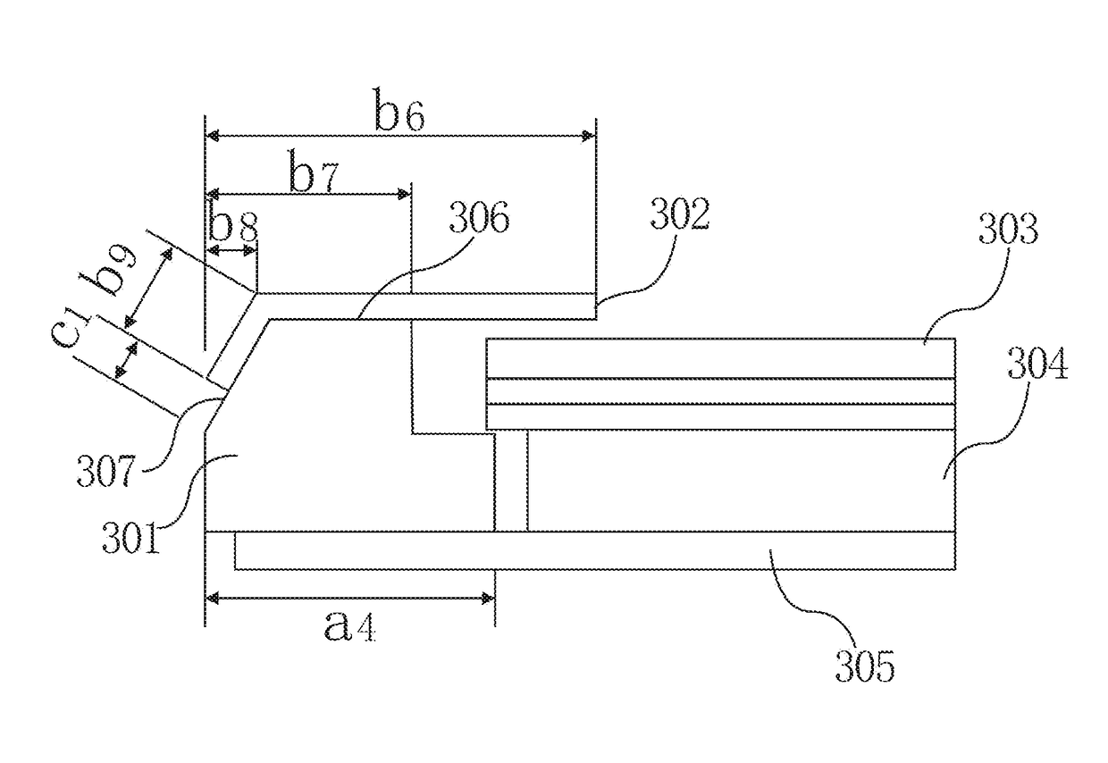
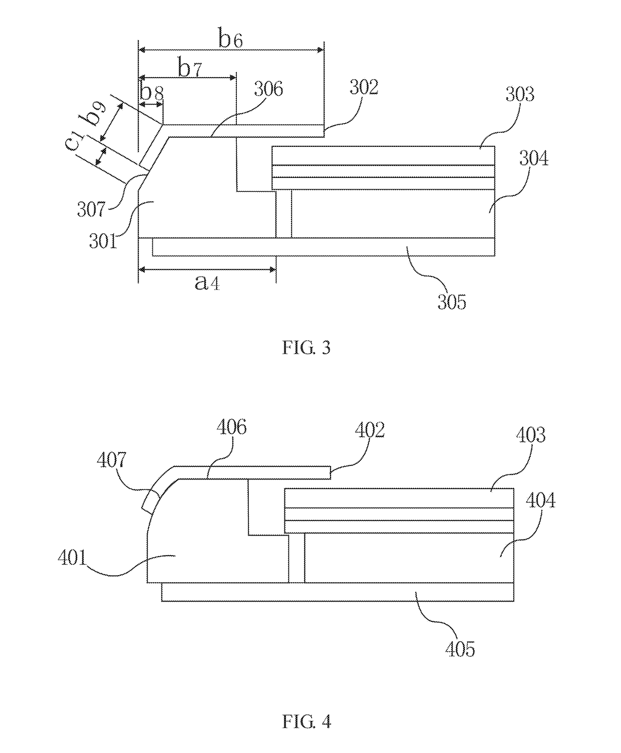
[0059]Please refer to FIG. 3, FIG. 3 is a schematic cross-sectional side view of a simplified structure of a backlight module according to the present invention.

[0060]The present invention provides a liquid crystal display apparatus. The liquid crystal display apparatus includes a backlight module positioned in a bottom position and a liquid crystal module positioned in a top position, wherein the backlight module in the bottom position provides a backlight source for the liquid crystal module in the top position. The liquid crystal module includes a bottom polarizing plate, a liquid crystal layer and a top polarizing plate which are orderly stacked.

[0061]As shown in FIG. 3, the backlight module includes a light guide plate 304, a reflector 305, a light source, an optical film 303, a plastic frame 301 and a square-shaped adhesive tape 302 adhered onto a surface of the plastic frame 301. The square-shaped adhesive tape 302 is used to adhesively attach the backlight module to the liqu...

second embodiment

[0067]Please refer to FIG. 4, FIG. 4 is a schematic cross-sectional side view of a simplified structure of a backlight module according to the present invention.

[0068]The present invention provides a liquid crystal display apparatus. The liquid crystal display apparatus includes a backlight module positioned in a bottom position and a liquid crystal module positioned in a top position, wherein the backlight module in the bottom position provides a backlight source for the liquid crystal module in the top position. The liquid crystal module includes a bottom polarizing plate, a liquid crystal layer and a top polarizing plate which are orderly stacked.

[0069]As shown in FIG. 4, the backlight module includes a light guide plate 404, a reflector 405, a light source, an optical film 403, a plastic frame 401 and a square-shaped adhesive tape 402 adhered onto a surface of the plastic frame 401. The square-shaped adhesive tape 402 is configured to adhesively attach the backlight module to th...

third embodiment

[0076]Please refer to FIG. 5, FIG. 5 is a schematic cross-sectional side view of a simplified structure of a backlight module according to the present invention.

[0077]The present invention provides a liquid crystal display apparatus. The liquid crystal display apparatus includes a backlight module positioned in a bottom position and a liquid crystal module positioned in a top position, wherein the backlight module in the bottom position provides a backlight source for the liquid crystal module in the top position. The liquid crystal module includes a bottom polarizing plate, a liquid crystal layer and a top polarizing plate which are orderly stacked.

[0078]As shown in FIG. 5, the backlight module includes a light guide plate 504, a reflector 505, a light source, an optical film 503, a plastic frame 501 and a square-shaped adhesive tape 502 adhered onto a surface of the plastic frame 501. The square-shaped adhesive tape 502 is configured to adhesively attach the backlight module to th...


PUM

PropertyMeasurementUnit
angleaaaaaaaaaa
widthaaaaaaaaaa
widthaaaaaaaaaa

Abstract

A backlight board and a liquid crystal display apparatus are disclosed. The backlight module includes a plastic frame and a square-shaped adhesive tape. The plastic frame has an attachment surface on the top surface of the plastic frame. The attachment surface includes a first attachment sub-surface and a second attachment sub-surface. The first attachment sub-surface is parallel with a light-exiting surface; the second attachment sub-surface is connected to an end of the first attachment sub-surface, and is at a predetermined angle in relation to a plane on which the first attachment sub-surface is disposed. A portion of the square-shaped adhesive tape that may extend outwardly from an edge of the plastic frame can be attached to a transitional surface to avoid extending out of the plastic frame.

Description

RELATED APPLICATIONS[0001]This application is a National Phase of PCT Patent Application No. PCT / CN2016 / 089720 having International filing date of Jul. 12, 2016, which claims the benefit of priority of Chinese Patent Application No. 201610435336.X filed on Jun. 16, 2016. The contents of the above applications are all incorporated by reference as if fully set forth herein in their entirety.FIELD AND BACKGROUND OF THE INVENTION[0002]The present invention relates to the technical field of liquid crystal display technology, and more particularly to a backlight module and a liquid crystal display apparatus having the same.[0003]With the development of mobile communication products and tablet computers, a lot of mobile phone manufacturers use “slim bezel” as a selling point to attract consumers. The width of a plastic frame of a backlight module is in direct relation to the border width of a mobile phone.[0004]In a traditional backlight module, a black-white double-faced or black-black do...

Claims


Application Information

Patent Timeline
Patent Type & Authority Patents(United States)
IPC IPC(8): G02B6/10G02B6/43G02B6/42F21V8/00G02F1/1335
CPCG02B6/0088G02F1/133608G02F1/133512G02B6/0081G02F1/133308G02F1/1336G02F2202/28G02B6/009G02F1/133317
Inventor XU, PENGBO
Owner WUHAN CHINA STAR OPTOELECTRONICS TECH CO LTD
Why Eureka
Try Eureka