Loop predictor-directed loop buffer

a technology of predictors and loop buffers, applied in the field of loop predictors, can solve problems such as pipeline bubbles, power consumption, and potential performance problems of loops

Active Publication Date: 2018-02-13
VIA ALLIANCE SEMICON CO LTD
View PDF12 Cites 2 Cited by
  • Summary
  • Abstract
  • Description
  • Claims
  • Application Information

AI Technical Summary

Benefits of technology

[0025]Conventionally, operating in loop buffer mode has involved effectively always predicting the loop branch instruction will be taken, which implies that upon loop exit, i.e., the last time the loop branch instruction is executed, a misprediction will occur that will have to be corrected by the processor 100. Advantageously, embodiments are described herein in which the loop predictor 102 operates in conjunction with the loop buffer 114 in loop buffer mode to potentially accurately predict the loop exit and thereby avoid the misprediction experienced by a conventional processor 100 not having the benefit of the loop predictor-directed loop buffer mode operation.

Problems solved by technology

Loops present a potential performance problem for modern processors because they include a conditional branch instruction, particularly for pipelined and / or superscalar processors.
Additionally, the decoding of the fetched instructions prior to issuance for execution may be complex, particularly for some instruction set architectures, and consequently introduce latency that may also cause pipeline bubbles.
Another concern in modern processors is power consumption.
For another example, in server environments, the presence of a relatively large—indeed sometimes enormous—number of servers results in a very significant cost in terms of power consumption, in addition to environmental concerns.
As discussed above, the decoding of instructions, including loop body instructions, may be complex and require a considerable amount of power to be consumed by the decode logic, in addition to the power consumed by the fetch logic and instruction cache from which the instructions are fetched and the branch predictors that predict the fetched conditional branch instructions of loops.

Method used


Image

  • Loop predictor-directed loop buffer
  • Loop predictor-directed loop buffer
  • Loop predictor-directed loop buffer

Examples


Embodiment Construction

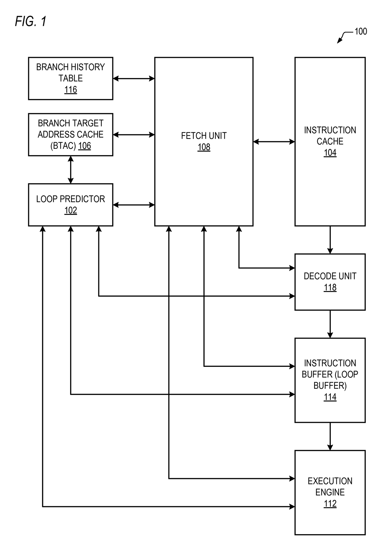
[0016]Referring now to FIG. 1, a block diagram illustrating a processor 100 is shown. The processor 100 includes a fetch unit 108 that controls fetching of instructions from an instruction cache 104 that are provided to an instruction decode unit 118. The decode unit 118 provides decoded instructions to an instruction buffer 114, also referred to herein as a loop buffer 114, which provides instructions to an execution engine 112 for execution. The fetch unit 108 is coupled to the decode unit 118, instruction buffer 114, and execution engine 112. The processor 100 also includes a plurality of branch predictors. In one embodiment, the branch predictors include a branch history table 116, a branch target address cache (BTAC) 106 and a loop predictor 102, each of which is coupled to the fetch unit 108. The loop predictor 102 is also coupled to the decode unit 118, instruction buffer 114 and execution engine 112.

[0017]For purposes of the present disclosure, a loop is a sequence of instru...


PUM


Abstract

A loop predictor trains a branch instruction to determine a trained loop count of a loop. When the loop fits in an instruction buffer, the processor stops fetching from an instruction cache, sends the loop instructions to an execution engine from the buffer without fetching from the cache, maintains a loop pop count of times the branch is sent to the execution engine from the buffer, and predicts the branch instruction is taken when the loop pop count is less than the trained loop count and otherwise predicts not taken.

Description

CROSS REFERENCE TO RELATED APPLICATION(S)[0001]This application claims priority to China Application No. 201410512577, filed Sep. 29, 2014, which is hereby incorporated by reference in its entirety.BACKGROUND[0002]Computer programs commonly contain loops. A loop is a sequence of instructions, commonly referred to as the loop body, which is executed repeatedly until a condition occurs that causes the loop to exit and proceed to the next instruction following the loop. At the machine language level, typically the loop ends with a conditional branch instruction that normally branches back to the instruction at the beginning of the loop body, but which is not taken and falls through to the next sequential instruction when the condition occurs. The condition may be, for example, that a variable, which was initialized to a positive value and then decremented each time through the loop, reaches zero.[0003]Loops present a potential performance problem for modern processors because they incl...

Claims


Application Information

Patent Timeline
Patent Type & Authority Patents(United States)
IPC IPC(8): G06F9/30G06F9/38G06F12/0875
CPCG06F9/3806G06F9/30065G06F12/0875G06F9/381G06F2212/452
Inventor CHEN, GUO HUAYANG, MENG CHENGAO, XIN YUGONG, FAN GONGHUANG, ZHEN HUA
Owner VIA ALLIANCE SEMICON CO LTD
Why Eureka
Try Eureka