Servo control method

Active Publication Date: 2020-08-20
ORMON CORP
View PDF0 Cites 1 Cited by
  • Summary
  • Abstract
  • Description
  • Claims
  • Application Information

AI Technical Summary

Benefits of technology

[0012]The present invention enables the operation of a controlled object to foll

Problems solved by technology

However, since a response lag inevitably occurs in each servo motor in general feedback control,

Method used


Image

  • Servo control method
  • Servo control method
  • Servo control method

Examples


embodiment

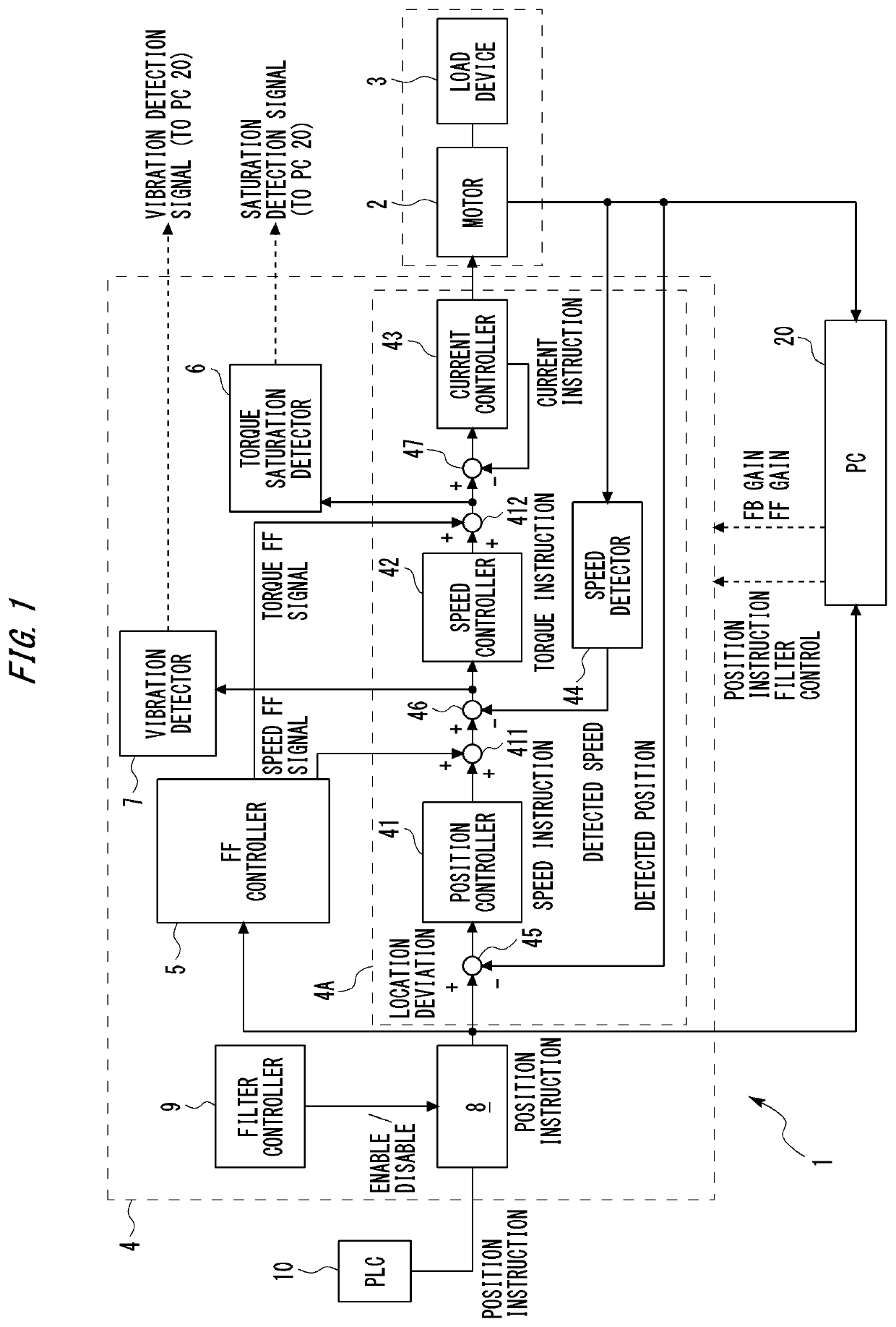
[0023]As described above, the servo control system 1 illustrated in FIG. 1 includes the controlled object 11 (motor 2 and load device 3), the servo driver 4, the PLC 10, and the PC 20. The servo driver 4 is electrically connected to the PLC 10 and the controlled object 11. Additionally, the servo driver 4 is capable of communicating with the PC 20. The communication may be wired communication or wireless communication.

[0024]In the servo control system 1, the servo driver 4 controls driving of the motor 2 and the load device 3, so that the operation of the controlled object 11 (motor 2 and load device 3) follows the position instruction (position target value) input from the PLC 10. Specifically, the servo driver 4 has multiple closed loops that control the rotation angle (position) of the motor 2, the rotation speed (moving speed) of the motor 2, and the generated torque of the motor 2, and can perform feedback control using the closed loops. Note, however, that feedback control doe...

operation example

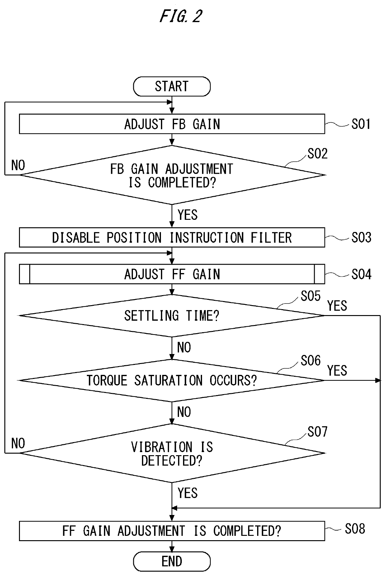
[0037]FIG. 2 is a flowchart describing an operation example of the servo control system 1. In the following operation example, it is assumed that the FB gain and the FF gain are adjusted manually by the operator by using the PC 20. Note, however, that the FB gain and the FF gain may be adjusted automatically. Additionally, while an example is illustrated in which the FB gain and the FF gain are adjusted by using the PC 20, an adjustment mechanism of the FB gain and the FF gain may be provided in the servo driver 4 and the PLC 10.

[0038]In FIG. 2, in S01, the FF controller 5 is inactive, and the FB gain (aforementioned position proportional gain, speed integral gain, speed proportional gain, torque proportional gain) used by the FB controller 4A is adjusted by using the PC 20. The FB gain can be increased and decreased in a stepwise manner. For example, assuming that the time required to obtain a detected position of the controlled object 11 for one position instruction input is one c...


PUM


Abstract

A servo control method includes a step of adjusting a feedback gain used in feedback control of a controlled object, the feedback control being performed based on difference information between a target value concerning an instruction and a feedback signal from the controlled object, so that the controlled object is operated by following the instruction, and a step of adjusting a feedforward gain used in feedforward control of the controlled object after the adjustment of the feedback gain.

Description

TECHNICAL FIELD[0001]The present invention relates to a servo control method for performing feedback control and feedforward control.BACKGROUND ART[0002]In order to move a controlled object in such a manner that it tracks a target trajectory, feedback control is generally used. For example, in an articulated robot, a control device of the robot uses feedback control to control a servo motor of each joint axis, so that the position of a hand unit of the robot tracks a preset (taught) target trajectory. However, since a response lag inevitably occurs in each servo motor in general feedback control, there is a problem that the actual trajectory of the robot deviates from the target trajectory. To address such a problem, there is a technique that adopts feedforward control to perform control so that the position of the robot may consistently match the instructed position.[0003]As a conventional technology for performing feedback control and feedforward control, there has been a servo co...

Claims


Application Information

Patent Timeline
IPC IPC(8): G05B11/36G05B11/32
CPCG05B11/32G05B11/36
Inventor NAKAJIMA, KENJIEGI, MAMORU
Owner ORMON CORP
Why Eureka
Try Eureka