Combined antenna apertures allowing simultaneous multiple antenna functionality

a technology of combined antenna aperture and antenna, applied in the field of combined antenna aperture, can solve the problems of limited number of antennas, dish needs to be pointed, and the operation of these products is limited to receiving

Active Publication Date: 2018-02-13
KYMETA
View PDF11 Cites 15 Cited by
  • Summary
  • Abstract
  • Description
  • Claims
  • Application Information

AI Technical Summary

Benefits of technology

[0058]Advantages of embodiments of the present invention include the following. One advantage is to increase data through-put through a given antenna area. For communication systems requiring simultaneous 2-way, multi-band, or multi-satellite links, this is an enabling technology. The advantages of this interleaving / combining approach become most obvious when liquid crystal display (LCD) technology is used to fabricate the antenna panels. This is because the driving switches can then be TFT's (thin film transistors), which are smaller than surface mount field effect transistors (FET) drivers, allowing for higher density interleaving. Note that the element density is still much less than the pixel density achieved by LCD manufacturers.

Problems solved by technology

There are a limited number of antennas that can receive multiple polarizations and frequencies simultaneously.
The operations of these products are limited to receive.
Two limitations of such dish-based antennas are that a dish needs to be pointed towards the satellite and that the angular difference between the look angles of 2 or more feeds within 1 reflector is limited to approximately 10 degrees, e.g., Slimline 5 (99°-119°).
However, there is no ability to point at more than 1 source simultaneously.
Furthermore, there is no system level allowance described giving sufficient isolation to support simultaneous transmit and receive operation.
This increases size, cost, weight and power.

Method used


Image

  • Combined antenna apertures allowing simultaneous multiple antenna functionality
  • Combined antenna apertures allowing simultaneous multiple antenna functionality
  • Combined antenna apertures allowing simultaneous multiple antenna functionality

Examples


an example system embodiment

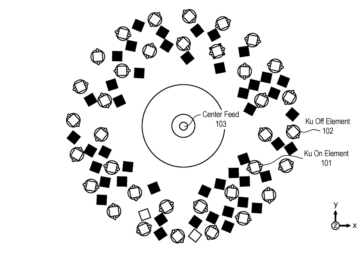
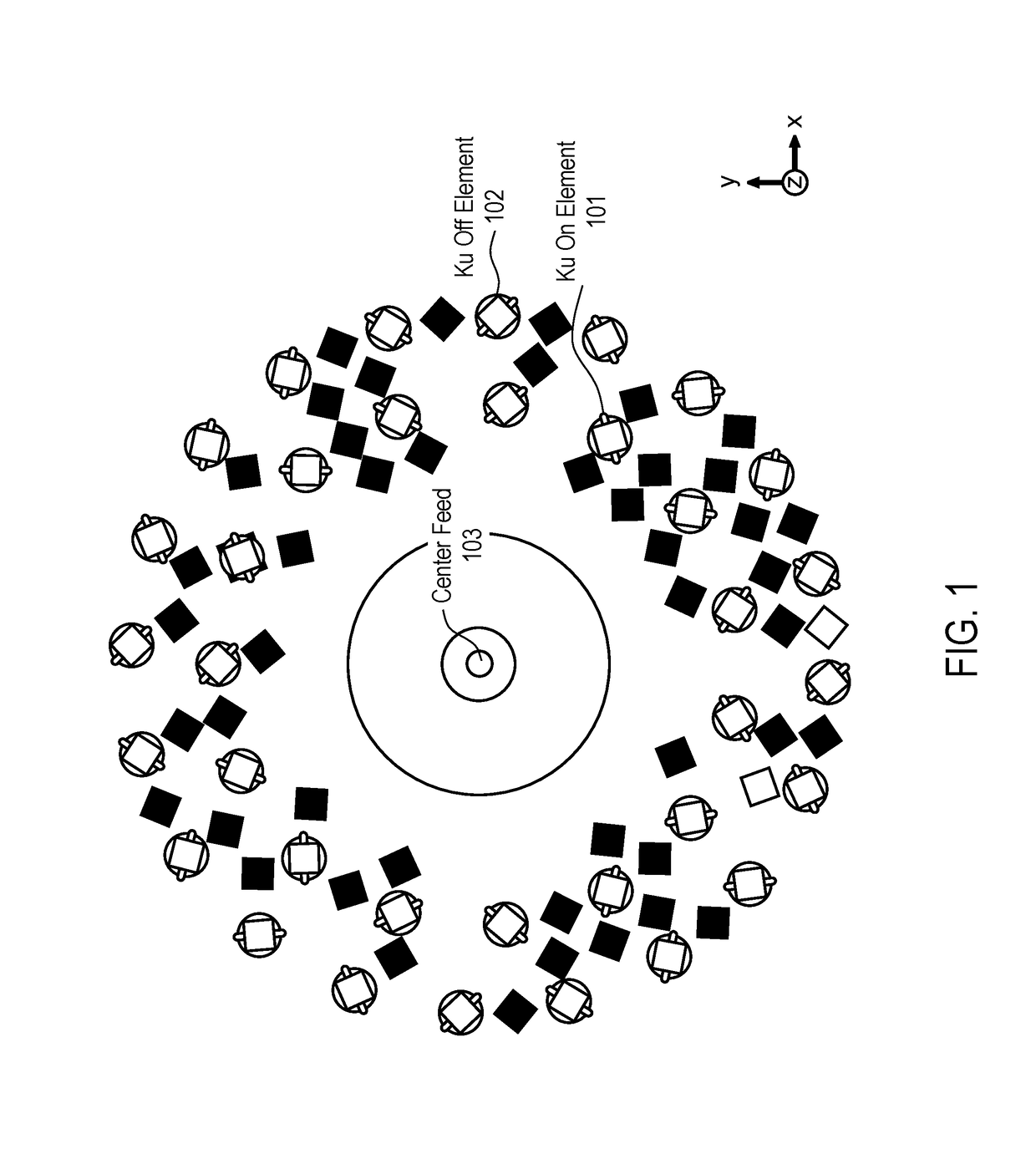
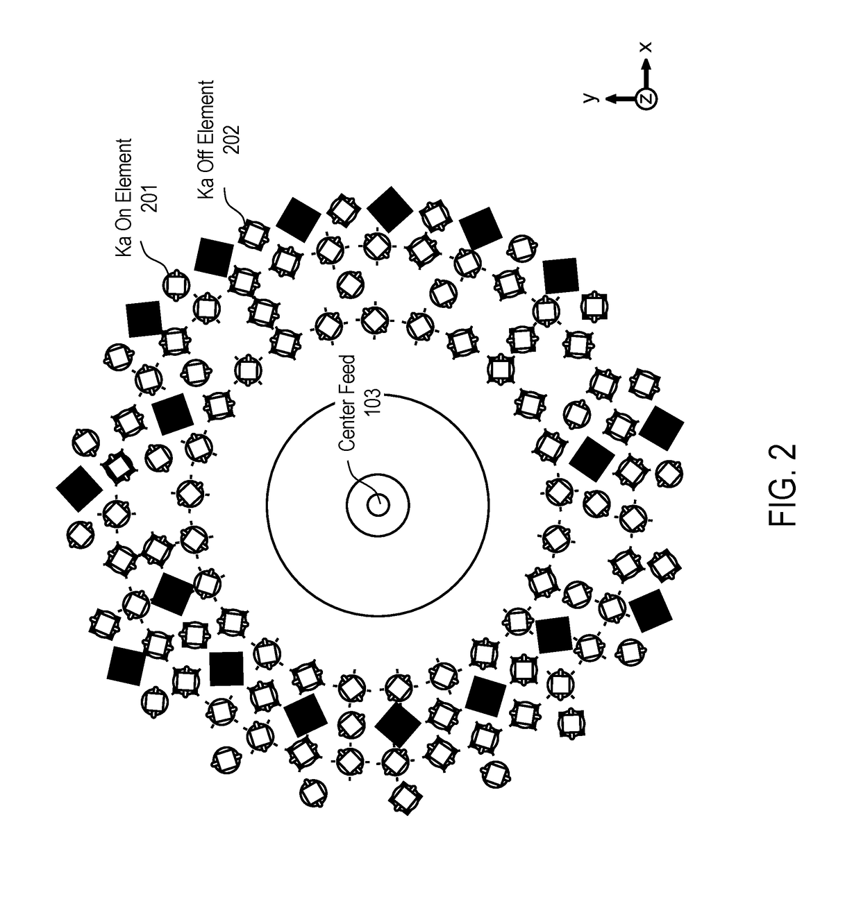
[0094]In one embodiment, the combined antenna apertures are used in a television system that operates in conjunction with a set top box. For example, in the case of a dual reception antenna, satellite signals received by the antenna are provided to a set top box (e.g., a DirecTV receiver) of a television system. More specifically, the combined antenna operation is able to simultaneously receive RF signals at two different frequencies and / or polarizations. That is, one sub-array of elements is controlled to receive RF signals at one frequency and / or polarization, while another sub-array is controlled to receive signals at another, different frequency and / or polarization. These differences in frequency or polarization represent different channels being received by the television system. Similarly, the two antenna arrays can be controlled for two different beam positions to receive channels from two different locations (e.g., two different satellites) to simultaneously receive multiple...


PUM


Abstract

An antenna apparatus and method for use of the same are disclosed herein. In one embodiment, the antenna comprises a single physical antenna aperture having at least two spatially interleaved antenna arrays of antenna elements, the antenna arrays being operable independently and simultaneously at distinct frequency bands.

Description

PRIORITY[0001]The present patent application claims priority to and incorporates by reference the corresponding provisional patent application Ser. No. 62 / 115,070, titled, “COMBINED ANTENNA APERTURES ALLOWING SIMULTANEOUS MULTIPLE ANTENNA FUNCTIONALITY,” filed on Feb. 11, 2015.FIELD OF THE INVENTION[0002]Embodiments of the present invention relate to the field of antennas; more particularly, embodiments of the present invention relate to an antenna having combined aperture that operates with multiple frequencies simultaneously using interleaved arrays.BACKGROUND OF THE INVENTION[0003]There are a limited number of antennas that can receive multiple polarizations and frequencies simultaneously. For example, the DirecTV Slimline 3 Dish reflector antenna receives multiple polarizations and frequencies simultaneously. In this product, there are 2 Ka-band receivers and 1 Ku-band receiver operating simultaneously from the same reflector. This is accomplished by placing multiple feeds at di...

Claims


Application Information

Patent Timeline
Patent Type & Authority Patents(United States)
IPC IPC(8): H01Q21/24H01Q25/00H01Q21/06H01Q21/00H01Q5/42H01Q21/30
CPCH01Q25/00H01Q5/42H01Q21/065H01Q21/061H01Q21/064H01Q21/0012H01Q3/247H01Q9/0457H01Q15/0086H01Q21/28H01Q25/002
Inventor BILY, ADAMSAZEGAR, MOHSENKUNDTZ, NATHANSTEVENSON, RYAN
Owner KYMETA
Why Eureka
Try Eureka