
Time of flight based passive entry/passive start system

a technology of time of flight and passive entry, applied in the field of time of flight estimation, can solve the problems of only utilizing power consumption when necessary, and achieve the effects of reducing energy consumption, increasing the delay between transmitted signals, and increasing the transmission of measurement duty cycl

Active Publication Date: 2018-02-13
GM GLOBAL TECH OPERATIONS LLC
View PDF10 Cites 16 Cited by
  • Summary
  • Abstract
  • Description
  • Claims
  • Application Information

AI Technical Summary

Benefits of technology

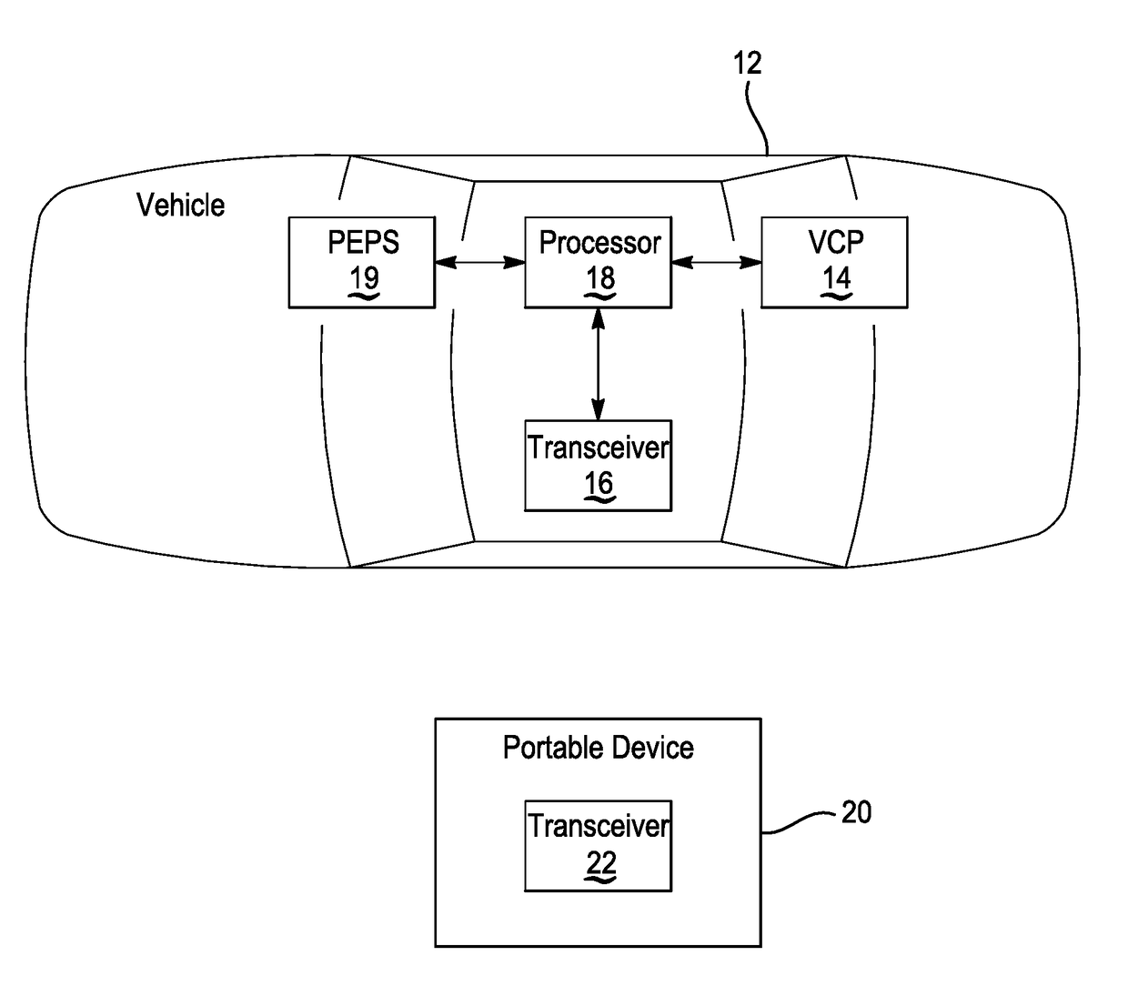
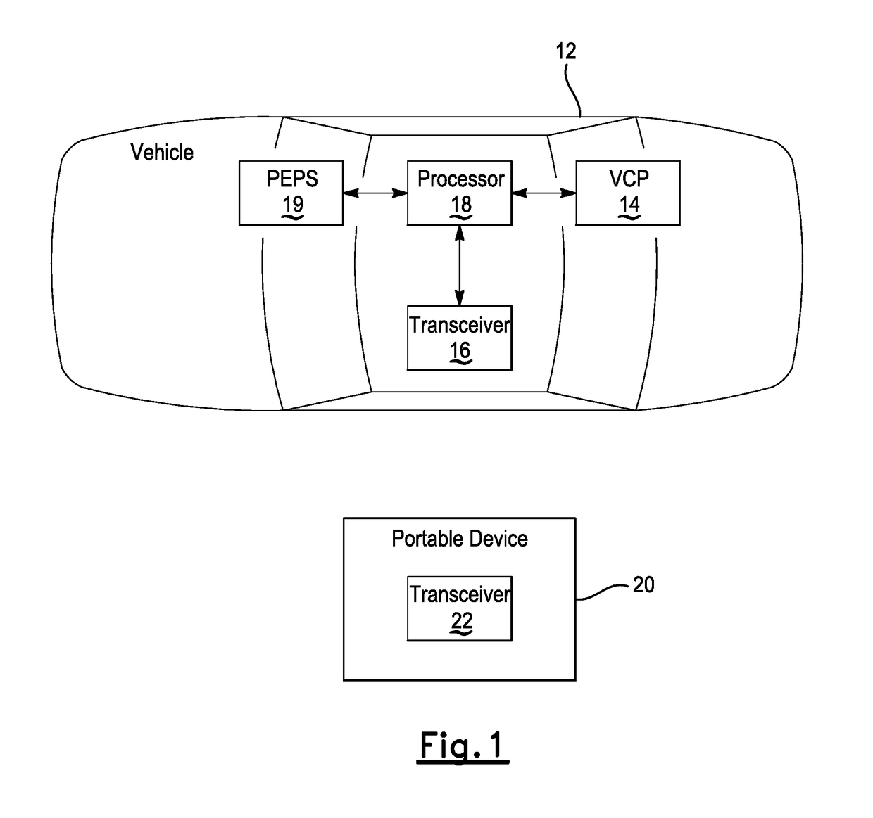
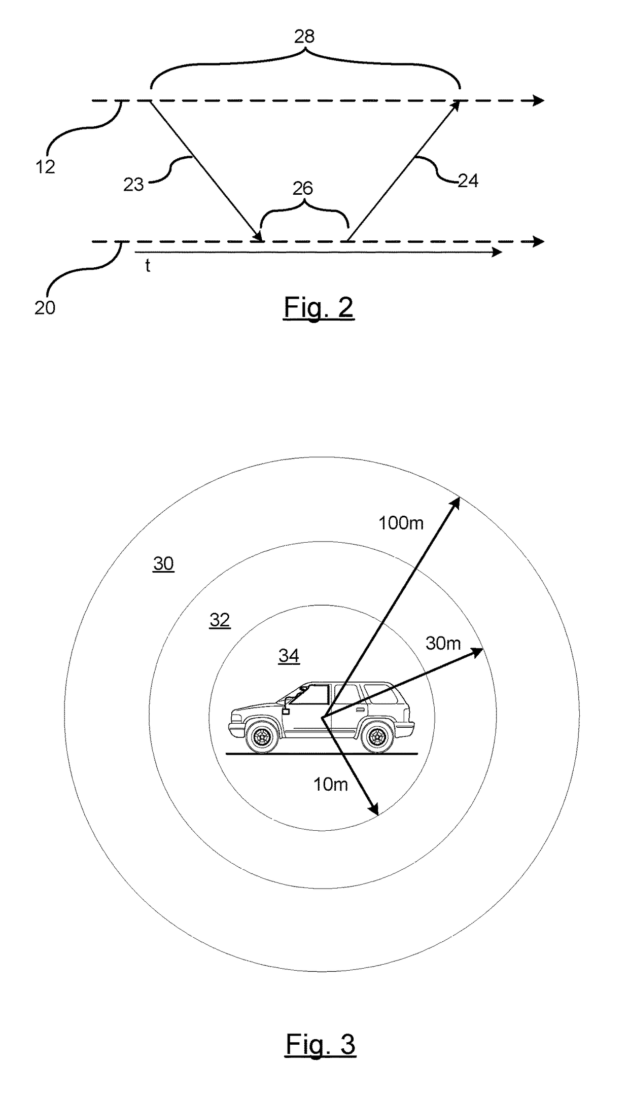
[0005]An advantage of an embodiment is dynamic adjustment of the duty cycle of an interrogation signal that reduces energy consumption. The system utilizes a plurality of predetermined transmission ranges relative to the vehicle, and based on what range the portable device is in determines the duty cycle of the interrogation signal. The system will initially transmit interrogation signals at a low measurement duty cycle (increased delays between transmitted signals) for detecting a remote device at a far distance from the vehicle. As the portable device is detected at closer ranges to the vehicle, the measurement duty cycle transmission is increased (smaller delays between transmitted signals). As a result, the system dynamically adjusts the duty cycle of the interrogation signal to conserve energy such that minimal power is utilized when the portable device is distal from the vehicle. As the portable device moves closer to the vehicle, the measurement duty cycle of the transmission is increased to maintain awareness of the approaching portable device. As a result, increased power consumption is only utilized when necessary, such as when the portable device gets closer to the vehicle where the location of the portable device must be constantly checked to determine if a vehicle operation should be actuated. The further the distance between the portable device and the vehicle, the less frequent the monitoring as it will take time for the portable device to approach the vehicle. Various techniques may be used to determine a location of the portable device such as Time-of-Flight or RSSI. In addition, an Angle-of-Arrival may also be to determine not only a position of the portable device but a direction of the approaching portable device.

Problems solved by technology

As a result, increased power consumption is only utilized when necessary, such as when the portable device gets closer to the vehicle where the location of the portable device must be constantly checked to determine if a vehicle operation should be actuated.

Method used


Image

  • Time of flight based passive entry/passive start system
  • Time of flight based passive entry/passive start system
  • Time of flight based passive entry/passive start system

Examples


Embodiment Construction

[0014]The following detailed description is meant to be illustrative in understanding the subject matter of the embodiments and is not intended to limit the embodiments of the subject matter or the application and the uses of such embodiments. Any use of the word “exemplary” is intended to be interpreted as “serving as an example, instance, or illustration.” Implementations set forth herein are exemplary and are not meant to be construed as preferred or advantageous over other implementations. The descriptions herein are not meant to be bound by any expressed or implied theory presented in the preceding background, detailed description or descriptions, brief summary or the following detailed description.

[0015]Techniques and technologies may be described herein in terms of functional and / or logical block components, and with reference to symbolic representations of operations, processing tasks, and functions that may be performed by various computing components or devices. Such opera...


PUM


Abstract

A passive entry-passive start portable device detection system. A portable device includes a transceiver. At least one vehicle-based transceiver broadcasts an interrogation signal. The transceiver of the portable device transmits a response signal in response to the interrogation signal. A controller determining at least a range of the portable device as a function of the time-of-flight of the interrogation and response signals. The controller controls a measurement duty cycle of the interrogation signal as a function of the determined range.

Description

CROSS-REFERENCE TO RELATED APPLICATIONS[0001]This application claims priority of U.S. Provisional Application Ser. No. 62 / 195,421 filed Jul. 22, 2015, the disclosure of which is incorporated by reference.BACKGROUND OF INVENTION[0002]An embodiment relates to time of flight estimation.[0003]Passive entry / passive start systems allow a user to passively enable entry to a vehicle or enable vehicle operations without having to directly utilize a key or manually actuate a fob for entering / starting a vehicle. Such passive systems operate by monitoring a proximity of a use carrying a passive device, such as a passive fob, on oneself, and when a trigger occurs such as touching of a door handle, the system will transmit an interrogation signal from which the fob transmits a reply signal. If the they vehicle and the fob carried by the user are successfully paired, then the doors will unlock without the user having to press an unlock key.[0004]Some passive systems operate based on a wakeup trigg...

Claims


Application Information

Patent Timeline
Patent Type & Authority Patents(United States)
IPC IPC(8): G08B1/08G07C9/00H04W52/02B60R25/24
CPCH04W52/0245B60R25/24G07C9/00309Y02D70/00G07C2209/08G07C2209/63B60R2325/103G07C2009/00547Y02D30/70
Inventor SCHEIM, KOBI J.LAIFENFELD, MOSHELAVI, NADAV
Owner GM GLOBAL TECH OPERATIONS LLC
Learn More