
Liner for cryogenic treatment systems

a cryogenic treatment system and liners technology, applied in the field of liners, can solve the problems of radiofrequency ablation, frequent lack of visualization, incomplete ablation, etc., and achieve the effect of preventing or inhibiting the fracturing or ripping of the lining

Active Publication Date: 2018-02-20
CHANNEL MEDSYST
View PDF56 Cites 1 Cited by
  • Summary
  • Abstract
  • Description
  • Claims
  • Application Information

AI Technical Summary

Benefits of technology

[0007]Because the liner is used to contact the tissue and thermally conduct the heat through the liner, the liner material may be comprised of various materials such as polyurethane, fluorinated ethylene propylene (FEP), polyether ether ketone (PEEK), low density polyethylene, polyethylene terephthalate (PET), polyvinylidene fluoride (PVDF), or any number of other conformable polymers. Moreover, the liner material may have a thickness which remains flexible and strong yet sufficiently thermally conductive, e.g., about 0.0005 to 0.015 in or about 0.001 in. on average. Such a thickness may allow for the liner to remain supple enough to conform desirably to the underlying tissue anatomy and may also provide sufficient clarity for visualizing through the material with, e.g., a hysteroscope.
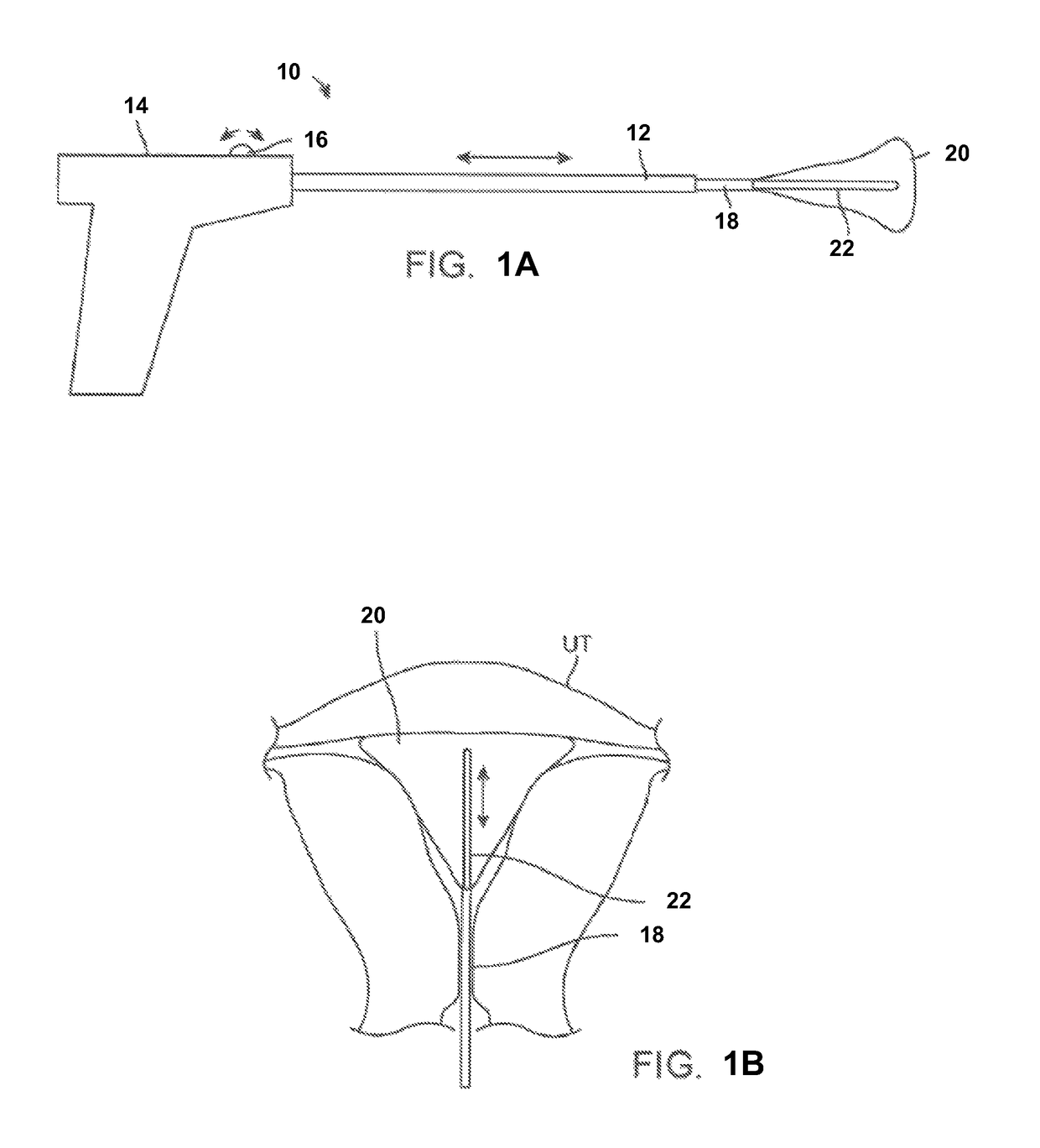
[0011]By translating the delivery line accordingly, the number of open delivery ports and closed delivery ports may be adjusted depending on the desired treatment length and further ensures that only desired regions of the uterine tissue are exposed to the infused cryogenic fluid or gas. Once the number of open delivery ports has been suitably selected, the infused cryogenic fluid or gas may bypass the closed delivery ports obstructed by the delivery line and the fluid or gas may then be forced out through the open delivery ports in a transverse direction as indicated by the infusion spray direction. The terminal end of the infusion line may be obstructed to prevent the distal release of the infused fluid or gas from its distal end. Although in other variations, the terminal end of the infusion line may be left unobstructed and opened.
[0012]Turning now to the liner itself, the liner may be formed to have, e.g., a nominal 0.001 in. (or more particularly 0.0012 in. +0.0004 / −0.0003) thick flexible membrane such as polyurethane or PELLETHANE® (Lubrizol Advanced Materials, Inc., Cleveland, Ohio). The liner 20 may be optionally formed as a composite from one or more sheets of material, e.g., two sheets of membrane which are RF welded. When laid out in a flattened shape, the liner may shaped in a manner which allows the liner to inflate or expand into a contoured shape which conforms closely to a uterine cavity. The liner itself may be formed to have a uniform thickness over the entire liner. Alternatively, different portions of the liner may also be formed to have differing thicknesses depending upon the desired degree of treatment along differing portions of the liner. For instance, the liner may have varying regions of thickness along proximal portions of the liner relative to distal portions of the liner.
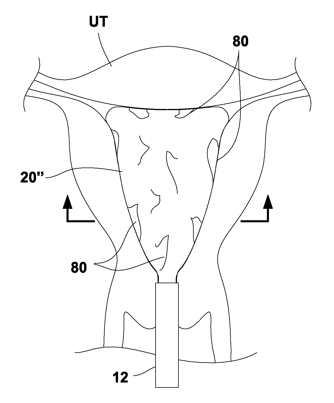
[0014]Because liner is constrained from fully expanding within the uterus, folds or portions of the liner may overlap upon itself over the surface of the liner in contact against the surrounding tissue. This is particularly so since the material of the liner may be non-distensible so as to prevent the full deployment of the liner within the uterine cavity. Even with folds or portions of the liner being folded upon itself, the liner may remain sufficiently supple such that the resulting uncontrolled folds allow for complete conformance of the liner against the anatomy of the contacted tissue. Moreover, the thickness of the liner may allow for the heat to be sufficiently conducted from the underlying tissue through, e.g., 1 to 3 layers of the liner, which may result in an overall thickness through the folded liner layers of, e.g., 0.001 to 0.003 in.
[0015]While the liner may be oversized to enable the liner to deliberately fold upon or over itself when contacting the underlying tissue, the formation of the folds or portions may occur randomly over the expanded liner. Alternatively, portions of the liner may be optionally pleated or folded such that liner expansion may preferentially cause these pleated or folded sections to fold against the surrounding tissue surface. Having the liner intentionally sized to be larger than the uterine cavity (or any other body lumen) into which the liner is placed may not only ensure that the liner is inhibited from over-expanding, but this also keeps the liner membrane from distending, particularly when frozen, so as to prevent or inhibit the liner from fracturing or ripping during or after treatment.

Problems solved by technology

While successful in several arenas, radiofrequency ablation has several major downsides, including incomplete ablation, frequent lack of visualization during catheter insertion, potential for overlap during treatment (with some areas receiving twice as much energy as other areas), charring of tissues and requirements for frequent debridement, frequent requirements for additional doses of energy after debridement, and potential perforation of the body cavity or lumen due to the rigidity of the RF electrodes.

Method used


Image

  • Liner for cryogenic treatment systems
  • Liner for cryogenic treatment systems
  • Liner for cryogenic treatment systems

Examples


Embodiment Construction

[0028]In treating an expandable and / or variably sized body lumen such as the uterus, a device generally having a cooling probe and a reconfigurable liner may be advanced within the body lumen and expanded into contact against the interior tissue surface. The liner may be configured to conform against the interior tissue surface and to resist rupture at low and high temperatures. For example, the liner when expanded may have a shape which approximates the body lumen in which it is inflated and / or come in various sizes to accommodate different patient anatomies. The liner may be formed to taper and have two rounded portions for expanding into intimate contact at the uterine cornu without painful deformation or distention of the uterus at a pressure, e.g., less than 150 mmHg.

[0029]Moreover, the liner may have a wall which is relatively thin (e.g., 0.040 in. or less) to facilitate thermal conduction through the liner material. The liner may also be sufficiently thin such that folding of...


PUM


Abstract

Liners for cryogenic treatment systems are described where a cryogenic fluid or gas may be introduced into a liner expanded within a body lumen such as the uterine cavity. The liner may be intentionally sized to be substantially larger than the typical size of the uterine cavity, e.g., 1.2 times (or more), greater than the size of the uterine cavity into which the liner is inserted. Because the liner is sized intentionally larger than the body lumen to be treated, the liner may never fully expand when deployed. But even with folds or portions of the liner being folded upon itself, the liner may remain sufficiently supple such that the resulting uncontrolled folds allow for complete conformance of the liner against the anatomy of the contacted tissue.

Description

FIELD OF THE INVENTION[0001]The present invention relates to medical devices. In particular, the present invention relates to methods and apparatus for liners which are used in therapeutic devices for cryoablating tissue in bodies with variable anatomy.BACKGROUND OF THE INVENTION[0002]In the last few decades, therapeutic intervention within a body cavity or lumen has developed rapidly with respect to delivery of energy via radiofrequency ablation. While successful in several arenas, radiofrequency ablation has several major downsides, including incomplete ablation, frequent lack of visualization during catheter insertion, potential for overlap during treatment (with some areas receiving twice as much energy as other areas), charring of tissues and requirements for frequent debridement, frequent requirements for additional doses of energy after debridement, and potential perforation of the body cavity or lumen due to the rigidity of the RF electrodes.[0003]The current state of the ar...

Claims


Application Information

Patent Timeline
Patent Type & Authority Patents(United States)
IPC IPC(8): A61B18/02A61B18/00A61B17/42
CPCA61B18/02A61B2017/4216A61B2018/0212A61B2018/00577A61B2018/00559
Inventor BURNETT, DANIEL R.MALECKI, WILLIAM
Owner CHANNEL MEDSYST
Learn More