Device and method for taking a high energy image

a high-energy image and image technology, applied in the field of high-energy image devices, can solve the problems of difficult adjustment of angiography system, difficult detection of stents in x-ray image, and difficulty in displaying biodegradable stents with sufficient contrast in x-ray images, so as to reduce the susceptibility to error and eliminate human error

Active Publication Date: 2015-10-06
SIEMENS HEALTHCARE GMBH
View PDF17 Cites 0 Cited by
  • Summary
  • Abstract
  • Description
  • Claims
  • Application Information

AI Technical Summary

Benefits of technology

[0008]Proceeding from this prior art, the object of the invention is to specify a device and a method for taking high energy images enabling adjuvants present in the object under examination to be displayed with good quality.
[0010]The device for taking high energy images has a control unit to which data relating to the medical adjuvant can be fed via an input device. The control unit is then able to set operating parameters of the imaging unit according to the adjuvant data in such a way that the high energy image taken reproduces both the adjuvant disposed inside the object under examination and the adjacent area with sufficient clarity. The device therefore eliminates the laborious process of searching for optimum settings for the imaging unit. Instead, knowledge already available about the nature of the imaging object is used to set the imaging unit accordingly.
[0011]In a preferred embodiment, the device is a device for taking a high energy image of a patient's body region into which a medical adjuvant such as a stent or contrast agent has been inserted. By entering the data relating to said medical adjuvant, the imaging unit can be adjusted by the control unit in such a way that the high energy images clearly show both the medical adjuvant and the adjacent regions of the body of the patient being examined.
[0012]In a further preferred embodiment, the device is equipped with a scanner with which adjuvant data can be read in from the adjuvant's packaging. The advantage of this embodiment is that data transfer is automatic, which eliminates human error when entering data.
[0013]In another preferred embodiment, the data relating to the adjuvant is stored in a memory which the control unit can access. The corresponding data record is then selected by entering a code identifying the adjuvant and the associated data record. With this embodiment it is therefore unnecessary to re-input the data record required for setting the imaging unit each time, thereby reducing the susceptibility to error.
[0015]In response to a user input, the device can preferably be placed in an operating condition in which the device takes the adjuvant data into account for adjusting the imaging unit. Such an embodiment of the device facilitates user guidance, as the new operating condition must be deliberately selected by the user in cognizance of the particular details.

Problems solved by technology

Reliably detecting stents in angiographic examinations is a major technical challenge, particularly in radioscopy mode.
As the stents are made by different manufacturers, they differ markedly in respect of material used and mechanical design, which makes it difficult to adjust the angiography system such that both the stent and the surrounding tissue are clearly discernible to medical personnel.
These additional coatings make it even more difficult to detect the stents in the x-ray image.
Such stents made of biodegradable material are difficult to show with sufficient contrast in x-ray images.

Method used


Image

  • Device and method for taking a high energy image
  • Device and method for taking a high energy image
  • Device and method for taking a high energy image

Examples


Embodiment Construction

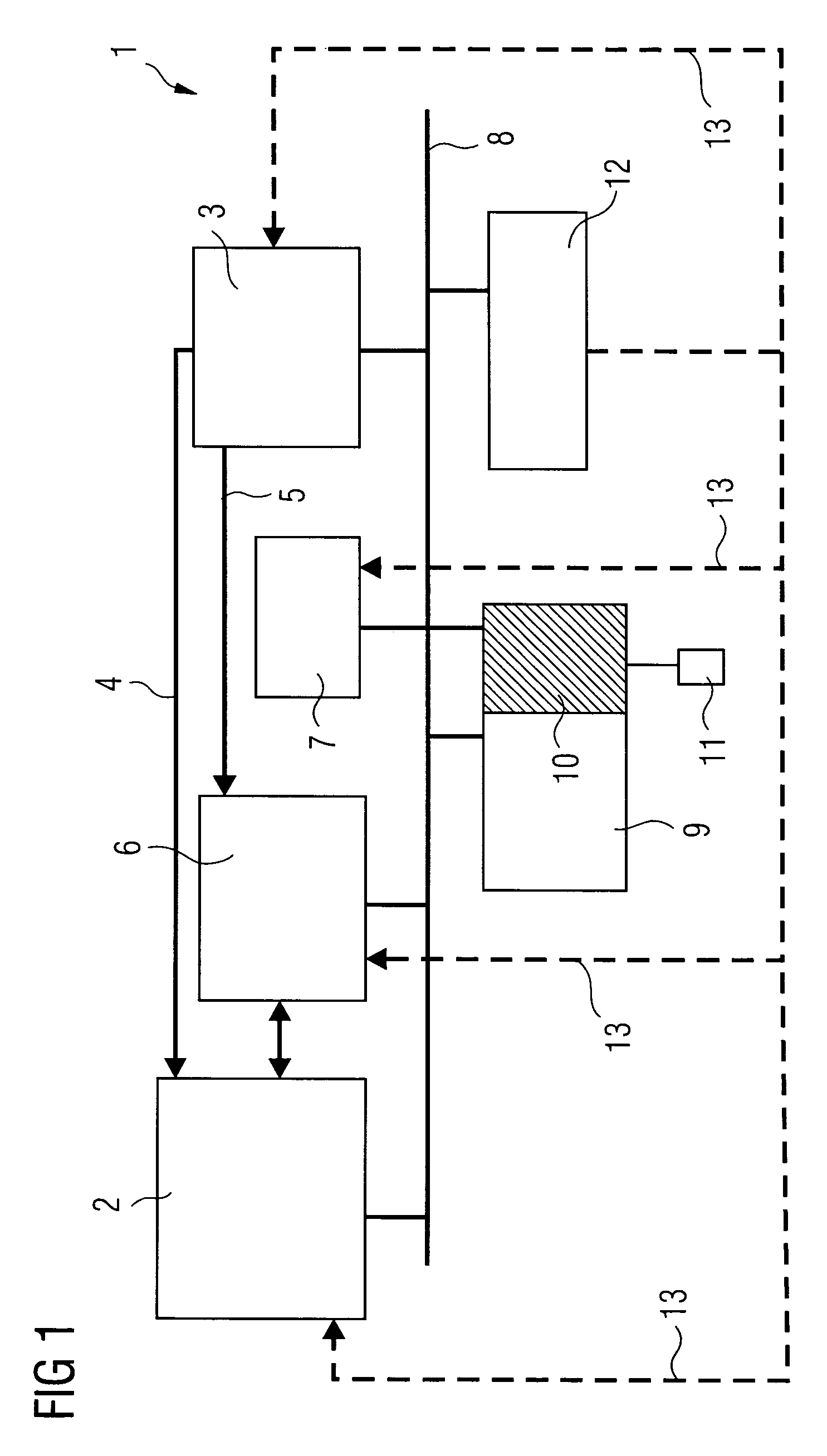
[0020]FIG. 1 shows an x-ray system 1 having a radiation source 2. The radiation source 2 comprises, for example, a high voltage generator and an x-ray emitter with different coiled filaments, beam apertures and various radiation filters. The radiation source 2 sends x-radiation (not shown in FIG. 1) to an x-ray detector 3 which is, for example, a flat-panel detector with additional dose measurement. The recording of the x-ray image is influenced using control data 4 on the part of the x-ray detector 3. In particular, after the start of recording, the radiation characteristics of the radiation source 2 are re-adjusted as a function of the x-radiation received by the x-ray detector 3, as the weight or size of a patient is only to a limited extent a measure of the x-radiation to be expected. Therefore, at the start of recording, an initial setting is generally used and re-adjusted as recording proceeds.

[0021]The taking of the x-ray image causes image data 5 to be generated in the x-ray...


PUM


Abstract

The invention relates to a device for taking high energy images, in particular, X-ray images, comprising an input image by means of which data for a medical auxiliary may be inputted into the device. Said medical auxiliaries are preferably stents or contrast agents which can be introduced into the body of a patient. The display unit of the device can thus be correspondingly set for the applied auxiliary.

Description

CROSS REFERENCE TO RELATED APPLICATIONS[0001]This application is the US National Stage of International Application No. PCT / EP2005 / 050248, filed Jan. 20, 2005 and claims the benefit thereof. The International Application claims the benefits of German application No. 10 2004 004 626.3 DE filed Jan. 29, 2004, both of the applications are incorporated by reference herein in their entirety.FIELD OF INVENTION[0002]The invention relates to a device for taking a high energy image of an object under examination into which an adjuvant can be inserted, said device comprising an imaging unit for taking the high energy image and a control unit which controls the recording of the high energy image.[0003]The invention further relates to a method for taking a high energy image.BACKGROUND OF THE INVENTION[0004]A device and method of this kind are known from DE 198 09 738 A1. The device disclosed here is an x-ray diagnostic device having a control unit for preadjusting the aperture settings required...

Claims


Application Information

Patent Timeline
Patent Type & Authority Patents(United States)
IPC IPC(8): A61B5/05A61B6/00A61B6/12A61B19/00
CPCA61B6/545A61B6/12A61B6/504
Inventor MASCHKE, MICHAEL
Owner SIEMENS HEALTHCARE GMBH
Why Eureka
Try Eureka