Article transport facility

a technology for transporting facilities and objects, which is applied in the direction of mechanical conveyors, loading/unloading, conveyors, etc., can solve the problems of increasing the complexity increasing the weight of the tilting prevention mechanism, and not being able to keep the transport device provided with such a tilting prevention mechanism from becoming complex and heavier, so as to reduce restrict the tilting of the transport device, and reduce the effect of the increase in the weight of the transport devi

Active Publication Date: 2018-02-20
DAIFUKU CO LTD
View PDF12 Cites 1 Cited by
  • Summary
  • Abstract
  • Description
  • Claims
  • Application Information

AI Technical Summary

Benefits of technology

[0004]To reduce the manufacturing cost, it is desirable to keep the structure of the transport device from becoming more complex while, to reduce energy consumption, it is desirable to reduce an amount of any increase in the weight of the transport device that travels along the travel path. In this respect, the technology of Patent Document 1 is such that the tilting of the transport device in the projected state (in which the second support component is in the projected position) is prevented only by the tilting prevention mechanism provided to the transport device. This tends to increase the complexity of the tilting prevention mechanism, and to increase also the weight of the tilting prevention mechanism. As a result, with the technology of Patent Document 1, it is not easy to keep the transport device provided with such tilting prevention mechanism from becoming complex and heavier.
[0005]Therefore, an article transport facility is desired in which the tilting of the transport device in a projected state can be restricted while the structure of the transport device can be kept from becoming more complex and an amount of any increase in the weight of the transport device can be reduced.
[0007]In other words, the article transport facility is provided with a support member capable of supporting the second support component from below, in the projected state. Therefore, in the projected state in which a large moment load tends to occur in the transport device because the second support component is in the projected position, the support member can receive a load due to the second support component which suspends and supports the first support component. Thus, the moment load that the transport device has to bear can be reduced by the corresponding amount. As a result, the magnitude of the moment load that the transport device bears can be reduced to within a proper range, in the projected state so that it becomes possible to restrict the tilting of the transport device.
[0008]And the support member is not a member provided to the transport device. The transport device only needs to have a structure to transmit a load to the support member. As such, an arrangement for receiving the load due to the second support component is realized by the support member while the structure of the transport device can be kept from becoming more complex and an amount of any increase in the weight of the transport device can be reduced. In addition, if and when a tilting prevention mechanism is provided to the transport device, in addition to the support member, it is possible to decrease the weight-bearing requirement for the tilting prevention mechanism by the corresponding amount. Thus, a tilting prevention mechanism having a relatively simple structure can be used. Therefore, even when a tilting prevention mechanism is provided to the transport device in addition to the support member, the structure of the transport device can be kept from becoming more complex and an amount of any increase in the weight of the transport device can be reduced, compared with when the support member is not provided.
[0009]As such, with the characteristic arrangement described above, an article transport facility can be provided in which the tilting of the transport device in the projected state can be restricted while the structure of the transport device can be kept from becoming more complex and an amount of any increase in the weight of the transport device can be reduced. Note that, since the support member is supported directly or indirectly by the ceiling, the support member can receive the load due to the second support component with stability. In addition, since the support member is provided such as to allow the vertical movement of the first support component with respect to the second support component, an article can be transferred between the transport device and the transport target while the support member receives the load due to the second support component.

Problems solved by technology

This tends to increase the complexity of the tilting prevention mechanism, and to increase also the weight of the tilting prevention mechanism.
As a result, with the technology of Patent Document 1, it is not easy to keep the transport device provided with such tilting prevention mechanism from becoming complex and heavier.

Method used


Image

  • Article transport facility
  • Article transport facility
  • Article transport facility

Examples


Embodiment Construction

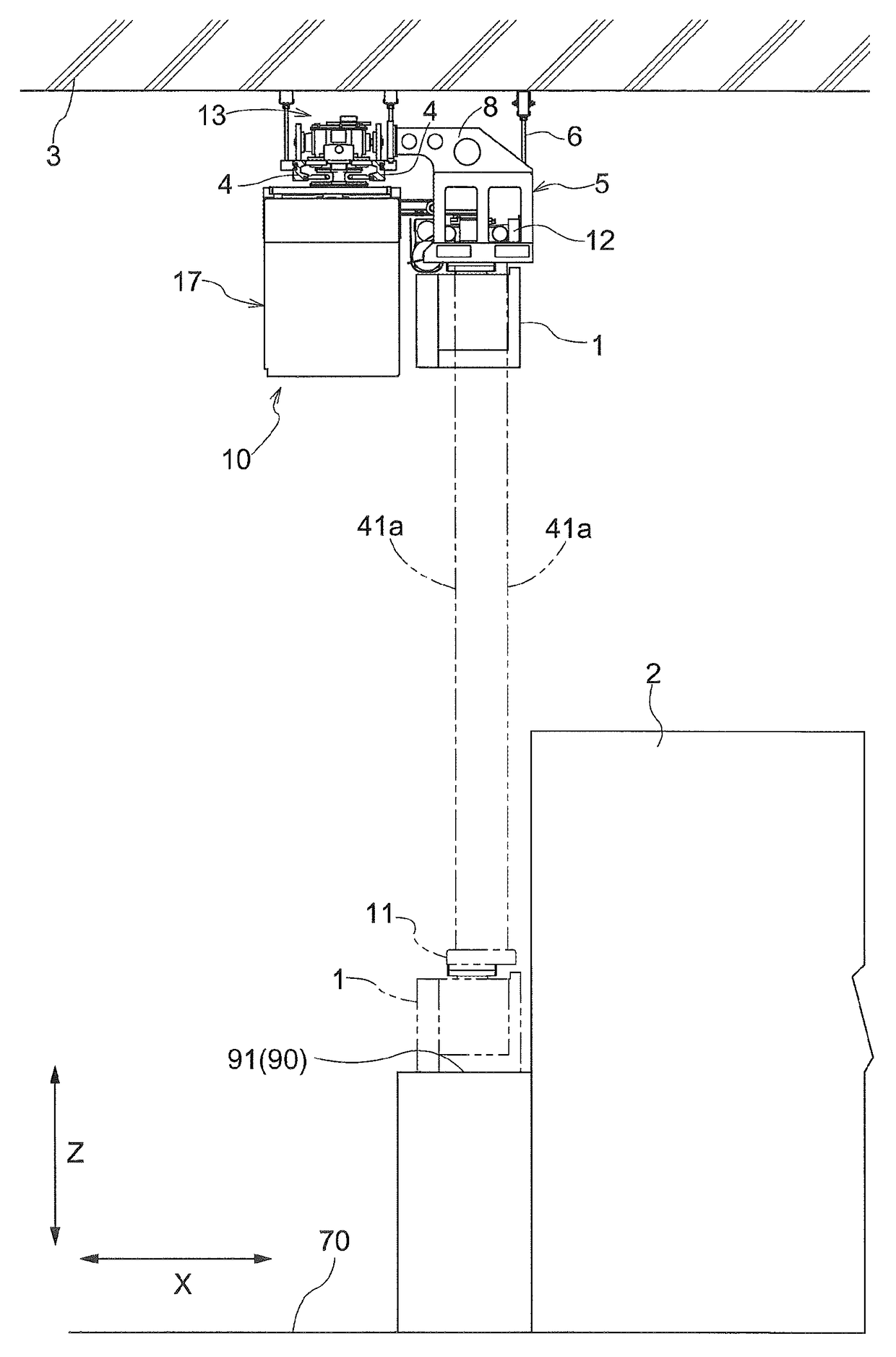
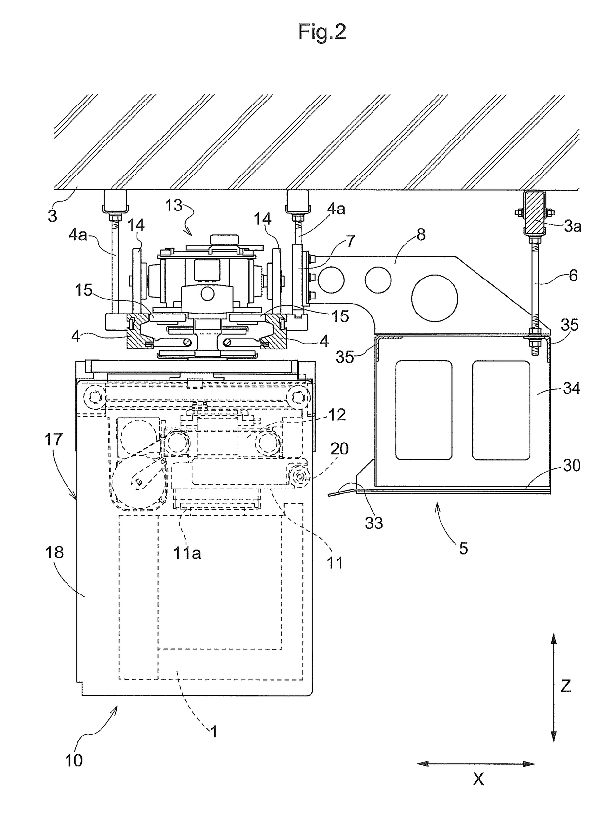
[0018]Embodiments of an article transport facility are described next with reference to the attached drawings. As shown in FIG. 5, the article transport facility includes one or more transport devices 10 and one or more transport target locations 90. Each transport device 10 travels along a travel path formed on the ceiling side (ceiling 3 side) to transport articles 1, one article at a time. Here, a travel path is an extent of the space in which the transport device 10 and the article 1 supported by the transport device 10 move when the transport device 10 travels. As shown in FIG. 2, in the present embodiment, when the transport device 10 travels, the article 1 is located within the main body portion 17 provided to the transport device 10. Thus, in the present embodiment, the space in which the article 1 moves when the transport device 10 travels is included in the space in which the transport device 10 moves when the transport device 10 travels.

[0019]The expression “formed on the...


PUM


Abstract

An article transport facility includes a support member capable of supporting a second support component from below while allowing a vertical movement of a first support component with respect to the second support component, in a projected state in which the second support component is located in a projected position. The support member is supported directly or indirectly by a ceiling.

Description

CROSS-REFERENCE TO RELATED APPLICATION[0001]This application claims priority to Japanese Patent Application No. 2015-225077 filed Nov. 17, 2015, the disclosure of which is hereby incorporated in its entirety by reference.FIELD OF THE INVENTION[0002]The present invention relates to an article transport facility comprising a transport device capable of traveling along a travel path formed on a ceiling side to transport an article, and a transport target location which functions as a transport origin or a transport destination for an article for a transporting operation by the transport device.BACKGROUND[0003]One known example of article transport facilities such as one described above is described in JP Publication of Application No. 2009-12916 (Patent Document 1). The transport device provided to the article transport facility of Patent Document 1 has a travel portion (travel portion 110) which travels in and along a travel path, a first support component (grip portion 150) that can ...

Claims


Application Information

Patent Timeline
Patent Type & Authority Patents(United States)
IPC IPC(8): B65G69/22H01L21/677H01L21/687
CPCB65G69/22H01L21/6773H01L21/67736H01L21/68707H01L21/67733B65G2201/0297B65G35/00B65G47/68B65G2201/0235H01L21/67706B65G49/061H01L21/67712H01L21/67718
Inventor TSUJI, TOMOHIKOASAHI, KAZUYA
Owner DAIFUKU CO LTD
Why Eureka
Try Eureka