Welding slag hammer

a technology of slag hammer and hammer head, which is applied in the direction of hand hammer, multi-purpose tools, hand chisels, etc., can solve the problems of requiring sharpening or even total replacement of the hammer, not only is it a costly endeavor, and the point becomes broken or dull

Inactive Publication Date: 2018-02-27
BAKER DANIEL E +1
View PDF21 Cites 7 Cited by
  • Summary
  • Abstract
  • Description
  • Claims
  • Application Information

AI Technical Summary

Benefits of technology

[0005]It is therefore the purpose of the inventor to provide a hammer comprising a head having a tip aperture located within a front end, a chisel located at a rear end, an impact area located on an upper face, a front shoulder disposed adjacent to

Problems solved by technology

Of course, over time, such points become broken or dull, and require sharpening or even total replacement of

Method used


Image

  • Welding slag hammer
  • Welding slag hammer
  • Welding slag hammer

Examples


Embodiment Construction

[0038]The best mode for carrying out the invention is presented in terms of its preferred embodiment, herein depicted within FIGS. 1 through 5. However, the invention is not limited to the described embodiment, and a person skilled in the art will appreciate that many other embodiments of the invention are possible without deviating from the basic concept of the invention and that any such work around will also fall under scope of this invention. It is envisioned that other styles and configurations of the present invention can be easily incorporated into the teachings of the present invention, and only one (1) particular configuration shall be shown and described for purposes of clarity and disclosure and not by way of limitation of scope.

[0039]The terms “a” and “an” herein do not denote a limitation of quantity, but rather denote the presence of at least one (1) of the referenced items.

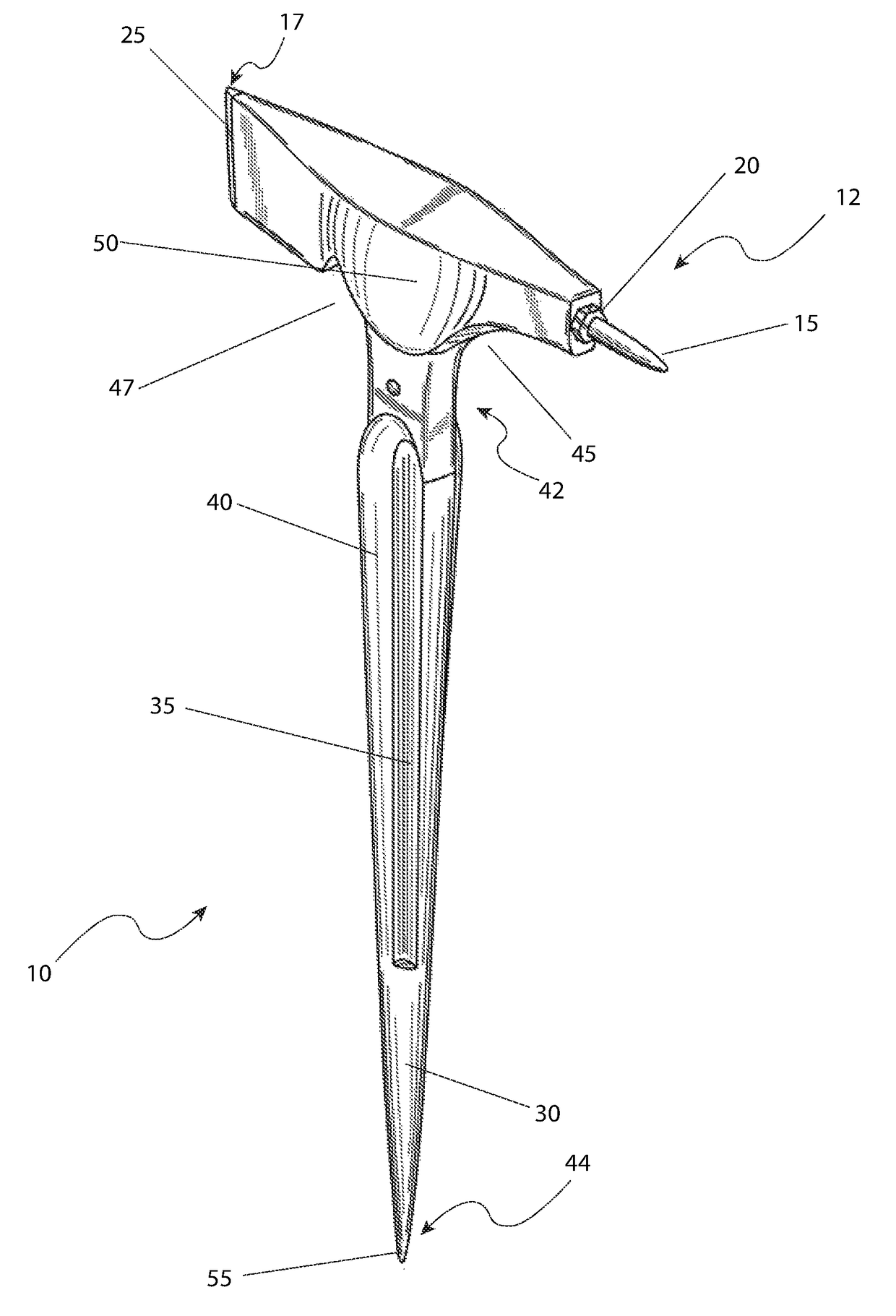
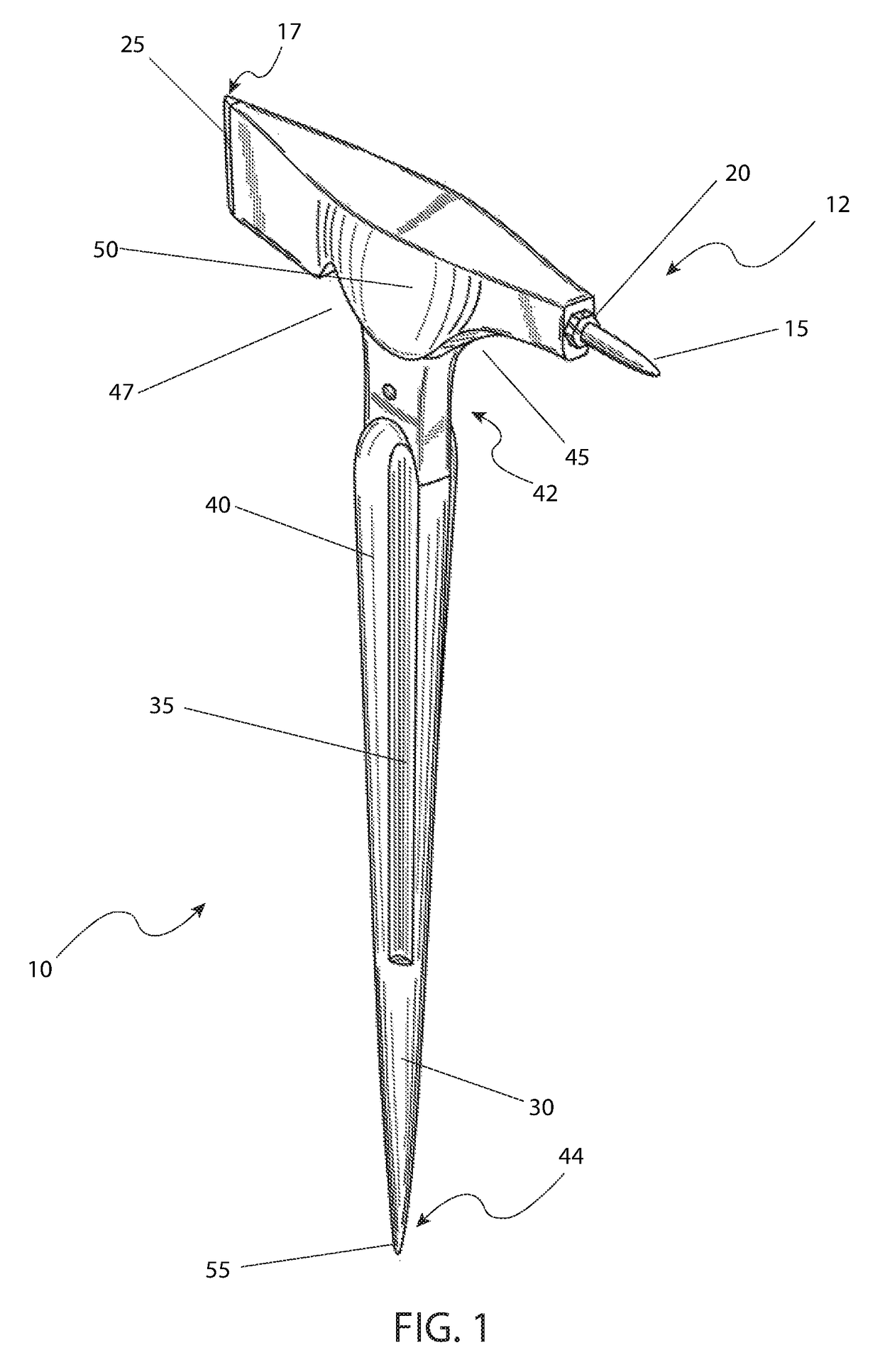
[0040]Referring now to FIG. 1, an isometric view of the welding slag hammer 10, according to the...


PUM


Abstract

A hand tool adapted to be used in the welding environment includes a handle and a head. The head includes a first end adapted to strike at and remove welding slag and a second end adapted to receive and retain a replaceable tip. The tip has two (2) opposable ends such that it can be reversed to extend the life thereof. The handle end, distal from the head, is operatively shaped to comprise a wedge and a pry surface.

Description

FIELD OF THE INVENTION[0001]The present invention relates generally to a welding slag hammer.BACKGROUND OF THE INVENTION[0002]Large construction steel erection projects require a variety of tools and accessories in order to produce a high-quality job in a minimum amount of time. One (1) of these tools that have been used for generations is that of the slag hammer. Such hammers are used to remove extra weld splatter and hard slag consisting of excess steel, flux, and other contaminants that exist near the side of weld. These hammers also typically permit a user to maneuver bolt holes into alignment and separate touching steel components by use of a wedge incorporated into the hammer's handle.[0003]Most slag hammers typically use a sharp pointed head to break through the crust of the slag. Of course, over time, such points become broken or dull, and require sharpening or even total replacement of the hammer. This not only is a costly endeavor, but slows down the work process while a n...

Claims


Application Information

Patent Timeline
IPC IPC(8): B25F1/00B25D3/00B25D1/02
CPCB25F1/006B25D3/00B25D1/02
Inventor BAKER, DANIEL E.BAKER, KANDIS S.
Owner BAKER DANIEL E
Why Eureka
Try Eureka